
© Joanna Walpole
C.2019
The contact patch
When you travel in a vehicle, it will speed up, slow down, and change direction many times during the journey. Manoeuvres like these can’t happen without help from the environment: forces must be applied to the vehicle from outside. A car, for example, needs a considerable push to accelerate to motorway speed, and an even larger one - in the opposite direction - to make it stop in an emergency. Lateral forces guide it round each curve. All of these forces must be channelled through the wheels, and in the case of any particular wheel, through the part of the tyre in contact with the road. Among motor engineers this is known as the contact patch. The contact patch limits what the vehicle can do. When driving on public roads, few of us are aware of this until things go wrong, whereas on a racing circuit, drivers think about their tyres all the time, trying to gauge the grip that remains in each tyre tread as it wears away during the race. To help them compete, racing tyre manufacturers make the contact patches as large and sticky as they can. A highly tuned engine and brakes are wasted if their output is too big for the tyres to handle.
How the wheels grip – or fail to grip – the surface involves some curious phenomena. The details are complicated, so manufacturers analyse tyre behaviour through a combination of mathematical analysis and computer simulation, then carry out exhaustive tests to make sure their products work properly [7]. In this Section, with the aid of a few simple diagrams we will try to understand what is going on, and leave the maths until later.
The footprint
A wheel on a railway wagon typically carries a load of 10 tonnes. It rests on a very small area about the size of your fingernail, say 10 mm across. The situation for road vehicles is different, for two reasons. First, the load is smaller, about half as much per wheel in the case of a heavy lorry. A saloon car, of course, is lighter still, with each front wheel typically carrying 450 kg, and each rear wheel about 300 kg. Second, the tyre spreads the load over an area roughly the size of a man’s foot, and although the surface it rests on is far from smooth, the rubber tread deforms around the peaks. Partly because of this deformation, rubber tyres grip much better than railway wheels, which is vital on a busy road, where car drivers are travelling close together without any central control.
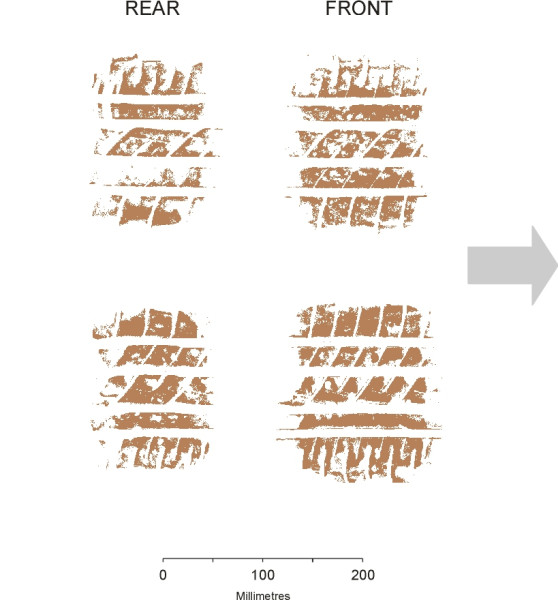
Pneumatic tyres are made in two different forms: radial ply and cross-ply (known as bias-ply in the USA - see Section C1610). Today, almost all cars use radial tyres; they deform in a different way from cross-ply tyres, and this is reflected in the shape of the contact patch. The outline is almost rectangular at normal loads, with rounded corners. If you jack up the wheel of your car you can make an image of the contact patch by inking the tyre and lowering the wheel onto a sheet of card backed with laminated chipboard. In figure 1, the prints of all four tyres of the author’s saloon are grouped together for comparison: the front axle of this car carries a little over 60% of the total weight, and this is reflected in the footprint sizes. Note that the dimensions change significantly when the vehicle is moving.
Figure 1
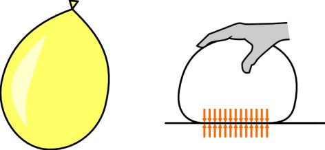
To a first approximation, the pressure of the tyre on the road surface is uniform across the whole area of the contact patch. This is because the enclosed air pushes out equally on all parts of the tyre, including the tread where it presses against the ground. Of course, real tyres have slots moulded into the tread that produce local stress concentrations, and to simplify matters, research on tyre behaviour is often carried out with the tread pattern removed. Here we’ll approximate the tread as a smooth continuous surface, and we’ll continue to do this in other Sections where it simplifies the analysis without greatly affecting the results. With this in mind we can now think of the carcass as thin and flexible like the skin of a balloon, with the pressures on either side of the membrane where it is flattened against the road surface approximately equal (figure 2). We can then calculate the size of the contact patch as the wheel load divided by the inflation pressure. Let’s take the car whose footprints are shown figure 1 as an example. The front tyres are inflated to approximately 220 kPa and each carries a load of about 460 kg when unladen. One might therefore expect the area of the contact patch to be 460 \(\times\) 9.81 /(1000 \(\times\) 220) = 0.0205 m2. The area enclosed by the outline of each front wheel print is in fact slightly greater than this, but if one allows for the slots between the tread blocks the true contact area comes to slightly less. The pressure isn’t in fact uniform, and as we shall later there are good reasons why this should be so.
Figure 2
Distortion of the carcass
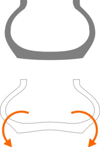
In order for the tyre contact area to lie flat on the road surface, the surrounding carcass must deform. Before going any further, it will be helpful to look at the nature of this deformation to see how it might affect the relationship between the tyre and the road. The most obvious deformation occurs in the walls, which bulge out on either side (figure 3). Repeated distortion of the tyre wall as the wheel rotates tends to overheat the carcass unless the wall is thin and flexible as is normally the case with radial tyres. However, even a thin wall resists bending to some extent, and in the process of deformation the wall transmits to the tyre tread within the contact patch a bending moment that tends to rotate the shoulder outwards as shown in figure 3. This is one of the reasons why the normal pressure distribution of the tyre on the road is not uniform.
Figure 3
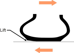
Side wall bulging is not always symmetrical. When a car goes round a curve, the contact patch deviates to one side and seen from above, the tread flows at an angle to the direction in which the wheel is pointing. In consequence, the cross-section of each tyre is distorted laterally as shown in figure 4. Particularly in the case of cross-ply (bias-ply) tyres, with extreme cornering forces it is possible for the inside edge of the tread to lift off the road surface, with an appreciable reduction in contact area and grip.
Figure 4
Standing wave
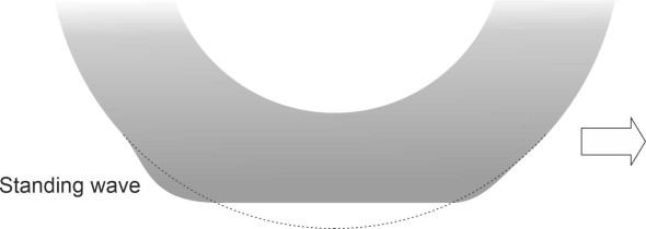
Less noticeable is a phenomenon that only occurs at higher speeds. When a tread element emerges from the contact patch there is a slight delay before it snaps back into its circular orbit, creating a longitudinal bulge outside the trailing edge (figure 5). This delay reflects the fact that a disturbance to the tread propagates at a finite speed around the tyre, in the same way that a wave travels at finite speed across a pond when you drop a stone in the water. Of course, the car wheel is rotating while the wave seems to stand still; hence it is referred to as a ‘standing wave’. It occurs most noticeably in cross-ply (bias-ply) tyres [4]. The wave travels at a fixed speed relative to the tyre, its value being determined by the tyre construction, ambient temperature and other factors. Let’s call it the ‘critical speed’. Clearly, when the car accelerates and the speed of the wheel increases, the tread will travel further round the wheel circumference before snapping back into its normal position. When the wheel speed approaches the critical speed, the wave will grow rapidly in size up to an amplitude of 10 mm and extend around a quarter of the tyre circumference [2]. At this point the wave absorbs a great deal of energy and the rolling resistance rises dramatically. When the wheel speed exceeds the critical value, by analogy with aerodynamics the wave becomes a shock wave, and the tyre is likely to disintegrate [5].
Figure 5
Effective rolling radius
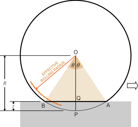
In principle, it’s easy to measure the size of a car tyre with a tape measure. But part of the tyre tread is flattened where it meets the road, and this flattening raises an interesting question. Since the perimeter is not actually circular, how do we define its radius? Suppose the distance between the axle centre and the undeformed part of the tread is \(R\). Then the distance measured from the axle centreline to the centre of the contact patch when the wheel is under load will be less than \(R\); we can write its value as \(R - z\) where \(z\) is the tyre deflection at the centre of the contact patch (figure 6). It seems obvious that, other things being equal, a loaded tyre will undergo more revolutions per kilometre of travel than an unloaded tyre whose tread is just touching the surface, and therefore the car designer needs to know the effective rolling radius\(R_{e}\) in order to calibrate the speedometer, work out suitable gear ratios, and estimate tyre wear for example.
Figure 6
If the tyre were made from a rigid material like glass, then relative to the vehicle each point on the periphery would move through the contact patch at a speed equal to the rate of rotation multiplied by the radius. So instead of measuring the radius directly we could measure the speed \(V\) of the vehicle together with the angular rate of rotation \(\Omega\), and deduce the radius as \(V/\Omega\). For a flexible tyre, therefore, it makes sense to define the effective rolling radius as
(1)
\[\begin{equation} R_{e} \quad = \frac{V}{\Omega}. \end{equation}\]If \(\Omega\) is measured in radians per second and \(V\) in metres per second, then \(R_e\) comes out in metres. There is another option: we can build a theoretical model that predicts the value of \(R_e\) based on the geometry of the tyre. But it’s more complicated than it looks.
The sliding spoke constraint
The reason is that the radius of any given tread element varies continuously as it moves through the contact patch. On entry at point A in figure 6 its radius is equal to the unloaded radius \(R\), but the value falls to \(R-z\) in the centre at Q, then rises to \(R\) again on exit at B. To predict the consequences, we must make some assumptions about the way each tread element is connected to its neighbours fore and aft, and also to the walls of the tyre on either side. One possibility is to treat it as a separate chunk of rubber that slides freely along a radial spoke that is rigidly attached to the wheel hub. We assume in effect that the tyre wall can flex to allow movement towards and away from the axle centreline, but being relatively stiff in shear it prevents circumferential movement altogether (figure 7).
Figure 7
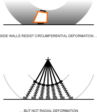
The sliding spoke constraint forces the tread to bunch up within the contact patch, with each element slowing down after entry to reach a minimum speed at the contact patch centre and then speeding up again until it re-emerges at the trailing edge. In the next section (C2015) we’ll try to work out the stresses this might cause between the contact patch and the road surface, but for now we are interested only in the speed of rotation. If we assume that the arc APB of the unloaded tread is compressed into the straight line distance AQB, we can work out a mathematical expression for \(R_{e}\) in terms of \(R\) and \(z\) by equating the average speed of the tread element to the speed of the road surface. The result, attributed to B D A Phillips of Coventry University, appears in [1]:
(2)
\[\begin{equation} R_{e} \quad \sim \quad R \left( 1 \; - \; \frac{z}{3R} \right). \end{equation}\]A slightly different derivation is set out in Appendix 1 at the end of this Section.
An alternative model might rely on assumptions that in a sense lie at the opposite extreme: we ignore the influence of the tyre walls and instead assume that the tread is incapable of stretching or compression. The analysis now becomes much simpler. By definition, the time taken for a single revolution of any wheel is \(2 \pi / \Omega\). Since the tread belt does not stretch or compress, in one revolution the wheel will travel a distance equal to the length \(2 \pi R\) of the belt, so its speed \(V\) must be equal to \(R \Omega\) [8]. Therefore
(3)
\[\begin{equation} R_e \quad = \quad R \end{equation}\]Equations equation 2 and equation 3 predict different values for \(R_e\) depending on the assumed behaviour of the tyre carcass. Working from different assumptions, others have arrived at different results.
Forces acting on the contact patch
If nothing else, the sliding spoke constraint serves to remind one that the tyre tread doesn’t unwind onto the road surface like a roll of wallpaper. Because of the flattened contact patch, the effective rolling radius is less than the unloaded radius of the tyre, and in free rolling the speed at which the tread moves around the unloaded perimeter is greater than the vehicle speed. But if we look more closely at the contact patch we see another reason why these two speeds might not be the same. It arises from strains within the sheet of rubber from which the tread itself is formed. During braking for example, when any given element of the tread arrives at the leading edge of the contact patch it is free of stress and free of deformation, but as it moves rearward the stress builds up and the rubber distorts progressively in shear in such a way that the lower face traverses the contact region more quickly than does the main body of the tyre (figure 8). Hence there is relative motion as if the tread were slithering across the surface like a snake, even though it remains firmly locked to the road surface throughout. The relative motion is called ‘creep’, and it occurs in all kinds of wheel including a steel wheel moving on a steel rail. Whenever it occurs, it signals the fact that the shear stress is not constant from place to place within the contact patch. We’ll examine this longitudinal variation shortly, but first, we’ll consider the normal pressure, whose behaviour is rather more straightforward and therefore easier to understand.
Figure 8

Normal pressure distribution
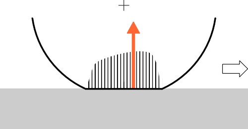
We mentioned earlier that to a first approximation, the carcass of a tyre acts like the skin of a balloon, and we might expect the pressure within the contact patch between the tyre and the road beneath to be roughly uniform. However, reality turns out to be more complicated. To begin with, the carcass acts to some degree as a load-bearing structure in its own right and therefore the tyre walls carry a proportion of the load directly to the ground via the shoulders - about 5% (figure 9). As a result, the pressure distribution within the contact patch is not uniform: the load carried by the tyre wall appears as a band of raised pressure along either side of the contact area, whose value is augmented by pressure arising from abrupt bending of the tread and walls (figure 10). Hence the pressure within the central part of the contact patch is a little less than one might otherwise expect. Using pressure sensors and a laboratory rig, it is possible to measure and plot these pressure variations in the form of contours. Examples of contour plots for stationary tyres can be found in [3], [6] and [9].
Figure 9
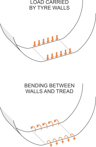
Figure 10
But the pattern changes when the wheel starts to roll: the centre of pressure moves forward of the axle centreline as shown in figure 11. It does so because the material is not strictly elastic. As we shall see later in Section C1717, each sector of the carcass undergoes a loading/unloading cycle as it passes through the contact patch, with the contact pressure higher during the loading part than it is during the unloading part owing to hysteresis in the rubber matrix. There is nothing mysterious about this: as explained in Section G1619, viscoelastic solids tend to absorb energy that is put into them when they are squeezed or stretched, energy that is not fully recovered when the load is removed.
Figure 11
Shear stress distribution
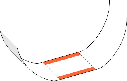
Now we can look at the most important stresses acting on the contact patch: the shear stresses that control the movement of the vehicle, make it go round corners, and slow it down under braking. In fact shear stresses occur even when the tyre is standing still. As shown in exaggerated form in figure 12, the tread contracts longitudinally towards the centre, rearward in the leading half of the contact patch and then forward again in the trailing half. The road surface resists the compression by applying a shear stress within the leading half of the contact patch that pulls the tyre forward, and another one acting on the trailing half that tends to pull it back (since they are equal and opposite, the two cancel out). And because of the bending in the side walls referred to earlier, there are shear stresses acting outward along either side. The resulting pattern is shown diagrammatically in figure 13. It appears as though the road surface is trying to drag the tyre tread apart, and conversely, as though the tyre tread were trying to draw the road surface inwards towards the centre of the contact patch.
When the wheel starts to roll the pattern changes. Assuming there are no external forces so the wheel turns freely within its bearing, we observe that the rearward-acting shear stresses grow a little in magnitude while the forward-acting shear stresses decline. The result is a small out-of balance residue that represents the tyre’s rolling resistance. In practice, as shown in figure 14 there may be a second stress reversal close to the trailing edge, and we’ll refer to this again in Section C2015. But it turns out that such stress reversals are prominent only when the tyre is rolling freely without any braking or traction applied to the wheel. Braking, for example, will impose a shear force acting on the contact patch against the direction of motion, which tends to dominate the stresses that arise in free rolling. The whole of the contact patch creeps forward along the road, and the greater the braking force, the faster it creeps (Section C0816). There is still variation in the longitudinal shear stress between different parts of the contact patch, but the direction of the stress is everywhere the same: towards the rear. We can quantify the variation if we are prepared to accept a simple rule governing carcass distortion such as the sliding spoke constraint, together with a model that relates stress to strains on the tread surface, and in Section C2015 we will do this by tracking the movement of a tread element through the contact patch and modelling its deformation as if it were an elastic bristle being deflected by the relative motion between the two surfaces. But for the moment, we will try to describe what is going on in qualitative terms.
Figure 12
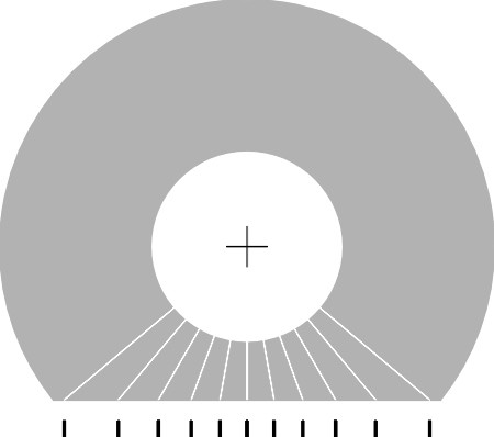
Figure 13
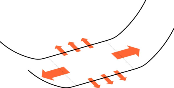
Figure 14
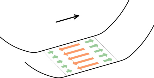
Stick and slip
Imagine a car being driven along a straight, level road. The driver applies the brakes, gently at first then with increasing pressure on the brake pedal. We know that the shear stress within any element of the tyre tread rises as it moves along the contact patch, starting from zero at the leading edge. When the driver presses harder on the brake pedal, the shear stress at the trailing edge will eventually reach a limiting value determined by the coefficient of friction of the rubber tread with the road. When this happens, the tread is no longer ‘locked’ to the road surface at the trailing edge, but free to slide rather than creep over the road surface. It still provides a braking effect, but no directional guidance. Any further pressure on the brake pedal has no effect on the shear stress; instead, the area over which slip occurs extends forward to cover a larger proportion of the contact patch. At the same time, within the leading part of the contact patch the tread is still locked to the road, so the rear portion cannot slide independently in some other direction, and there will be no outward sign of movement. As shown in figure 15, the two parts of the contact patch exist simultaneously in two different states of friction, one slipping and the other locked. (Interestingly, much the same happens when the driver applies the brakes of a railway train: as will be described in Section R2019, the contact patch divides into two zones, with the ‘slip’ region at the rear and the ‘stick’ region at the front - it is a universal characteristic of a rolling wheel for the contact area to divide into two sectors in this way.)
Figure 15
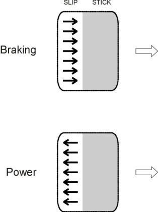
As the intensity of braking increases, the area of ‘slip’ continues to grow in size towards the leading edge of the contact patch, but there is still an area at the front that remains in normal rolling contact so that the wheel continues to provide lateral guidance (albeit reduced) and the car can be steered in a purposeful manner. However, the rate of creep within the ‘stick’ region now rises to a high level, and in fact the maximum friction occurs when the contact patch is creeping along the road at a speed around 10-20% of the speed of the car itself. At this point, the ‘slip’ area extends over the whole contact patch and any further increase in braking effort will cause the wheel to slide out of control.
Of course, there are other ways in which a tyre can be made to slide bodily over the road surface: for example, if you apply a burst of engine power to a driven wheel, it will undergo a similar process. As the power level rises, a slip region will appear at the trailing edge of the contact patch that extends forward and eventually covers the whole; the only difference is the direction of stress, which now pulls the wheel forwards rather than dragging it back. Finally, if you steer round a corner and rotate the handwheel to force the car into an increasingly severe turn, the shear stress within each contact patch develops in a similar way, except that its direction is from side-to-side rather than fore-and-aft. In this case the slippage is more obvious because as we shall see in Section C2015, the tyre rolls at an angle to the plane of the wheel.
Conclusion
Although we cannot be sure about the details, it seems that even when it is rolling freely without any traction or braking forces, a pneumatic tyre displays an interesting pattern of stresses and strains within the contact patch. There is at least one stress reversal as the material within the trailing half ‘creeps’ forward over the road surface, while that in the leading half creeps in the opposite direction, towards the rear. During more energetic manoeuvres the stress reversals disappear and the whole contact patch creeps in the same direction, but there is a distinct transition from ‘stick’ to ‘slip’ towards the trailing edge. Both the area of slip and the rate of creep continue to grow until the whole contact patch reaches a state of saturation and the tyre as a whole slides across the road surface. Hence the transition from normal rolling motion to an uncontrollable skid is not totally abrupt, and in this sense at least, our tyres are not glued to the road as firmly as we might imagine. In the next section we shall try to quantify the motions and forces using a model that may not be very realistic but goes some way towards explaining why tyres behave in the way they do.
Appendix 1: A formula for the effective rolling radius
Referring to figure 6, we picture the vehicle as stationary with the road passing underneath from right to left at speed \(V\). We assume that the time taken by any given element of the tyre tread to travel the length of the contact patch between A and B is the same as the time taken by any given element of the road surface to cover the same distance; in other words, the tyre tread moves through the contact patch at an average speed equal to the speed \(V\) of the road surface. Since the distance AQ is equal to \(R \sin \theta\), the time taken for a given element within the tyre tread to move from A to Q is equal to the distance it travels divided by its speed, i.e., \(R \, \sin \theta / V\). During this time the wheel turns through angle \(\theta\), so the angular rate of rotation \(\Omega\) is given by
(4)
\[\begin{equation} \Omega \quad = \quad \frac{\theta}{( R \, \sin \theta / V )} \quad = \quad \frac{V \theta}{R \sin \theta} \end{equation}\]Hence by definition
(5)
\[\begin{equation} R_{e} \quad = \quad \frac{V}{\Omega} \quad = \quad \frac{R \, \sin \theta}{\theta} \end{equation}\]We therefore need to find an expression for \(( \sin \theta / \theta )\) in terms of \(R\) and \(z\). For small \(\theta\) we can apply the well-known power series expansion for \(\sin \theta\) thus:
(6)
\[\begin{equation} \sin \theta \quad = \quad \theta \; - \; \frac{1}{3!}\theta^{3} \; + \; \frac{1}{5!} \theta^{5} \; + \; O(\theta^{7}) \end{equation}\]If we substitute this expression for \(\theta\) and cancel the common factor \(\theta\) from the numerator and denominator, equation 5 becomes
(7)
\[\begin{equation} R_{e} \quad = \quad R \left( 1 \; - \; \frac{1}{3!} \theta^{2} \right) \; + \; O (\theta^{4}) \end{equation}\]Now put
(8)
\[\begin{equation} \epsilon \quad = \quad \sin \theta \end{equation}\]so that
(9)
\[\begin{equation} \theta \quad = \quad \arcsin \; \epsilon \end{equation}\]Now the right-hand side can be expressed as a standard power series in \(\epsilon\) whence equation 9 becomes:
(10)
\[\begin{equation} \theta \quad = \quad \epsilon \; + \; \left( \frac{1}{2} \right) \frac{\epsilon^3}{3} \; + \; \left( \frac{1}{2} \right) \left( \frac{3}{4} \right) \frac{\epsilon^5}{5} \; + \; O \left( \epsilon^{7} \right) \end{equation}\]in other words
(11)
\[\begin{equation} \theta \quad = \quad \sin \theta \; + \; O (\sin^{3} \theta) \end{equation}\]and squaring both sides, we get
(12)
\[\begin{equation} \theta^{2} \quad = \quad \sin^{2} \theta \; + \; O (\sin^{4}\theta) \end{equation}\]Now, from triangle OAQ in figure 6 one sees that
(13)
\[\begin{equation} \sin \theta \quad = \quad \frac{AQ}{OA} \quad = \quad \frac{\sqrt{ R^{2} \, - \, \left( R - z \right)^2}}{R} \quad = \quad \frac{1}{R} \sqrt{2Rz \, - \, z^{2}} \end{equation}\]so that
(14)
\[\begin{equation} \sin^{2} \theta \quad = \quad \frac{z}{R} \left(2 \; - \; \frac{z}{R} \right) \end{equation}\]and substituting for \(\sin^{2} \theta\) on the right-hand side of equation 12 leads to
(15)
\[\begin{equation} \theta^{2} \quad = \quad \frac{2z}{R} \; + \; O \left( \frac{z}{R} \right)^2 \end{equation}\]which if substituted in turn for \(\theta^{2}\) on the right-hand side of equation 7 leads finally to the result
(16)
\[\begin{equation} R_{e} \quad = \quad R \left(1 \; - \; \frac{z}{3R} \right) \; + \; O \left( \frac{z}{R} \right)^2 \end{equation}\]Acknowledgement
Photo on opening page by Joanna Walpole: Bentley sports car at Goodwood