© Tom Wright
C.0415
Cornering basics
A motor race is not always won by the fastest car. It is won by the car that travels round the circuit in the shortest time, which is not quite the same thing. Much depends on how fast the driver can go round the slower parts of the circuit - the corners. For each corner, skilful handling can shave a fraction of a second off the lap time, and it is here where the best drivers make their mark. Of course, careering round a bend imposes large \(g\)-forces on the human body. The edges of the seat, the seatbelt and cockpit walls press on the thighs and torso with a total value of two or three times the driver’s body weight. If you aspire to be F1 champion, where other athletes have strong arms and legs, you will need a strong neck – to stop your head flopping from side to side as you snake through the chicanes.
Steady-state cornering
What are these forces and where do they come from? To travel round a curve of constant radius \(R\), the car and its passengers must be propelled sideways by a force directed towards the centre of the curve, in the same way that the hammer swung by an Olympic athlete is constrained by its chain. It is the tensile force in the chain that keeps the weight on a curved path. Only when the chain is released does the weight fly off in a straight line. If the mass of the vehicle is \(M\) and its speed is \(V\), the centripetal force \(C\) needed to keep it on a curve of radius \(R\) is given by
(1)
\[\begin{equation} C \quad = \quad \frac{MV^2}{R} \end{equation}\]The centripetal force is applied to the car through the four contact patches. But the car needs more than centripetal force: it must yaw as well. This means changing the heading – the horizontal direction in which it is pointing. It’s not instantaneous, but once the yaw has begun, it will continue steadily without any additional forces from the contact patches. From that point on, travel at a steady speed \(V\) round a curve of constant radius \(R\) can be pictured as a ‘steady state’ process because as far as the car is concerned, nothing changes from one moment to the next: a snapshot of what is happening at any given moment will look exactly like a snapshot taken several seconds earlier or later. So the cornering manoeuvre can readily be analysed to provide a baseline against which more complicated aspects of vehicle handling can be assessed.
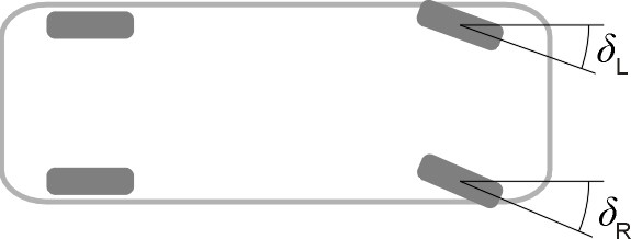
Figure 1

In figure 1, a vehicle is pictured in just such a situation. The left front wheel is positioned at an angle \(\delta_L\) relative to the vehicle’s longitudinal axis, and the right front wheel at an angle \(\delta_R\). These two angles are referred to as the steering angles for the left and right front wheels respectively. We can simplify the analysis by substituting a single wheel at the front and a single wheel at the rear as shown in figure 2. The steering angle \(\delta\) for the front wheel lies between \(\delta_L\) and \(\delta_R\), its value defined in such as way as to yield the same path as the original vehicle. The result is sometimes referred to as a ‘bicycle’ model, but since the word ‘bicycle’ in this context could be misleading we shall call it the ‘thin car’ model instead.
Figure 2

The model can help us to determine relationships among the variables we are interested in: for example, the rate of yaw \(\omega\) (the rate at which the car changes heading, in radians per second), the speed \(V\), and the curve radius \(R\). These three variables are connected by a relationship such that if any two are known, the third can be deduced immediately. Suppose the car travels round a complete circle. Its longitudinal axis sweeps out an angle \(2 \pi\) radians. The distance travelled round the circumference of the circle is \(2 \pi R\), and the time taken is equal to this distance divided by speed, or \(2 \pi R / V\). Hence the yaw rate is given by the formula
(2)
\[\begin{equation} \omega \quad = \quad \frac{2 \pi}{\left( {2 \pi R} / V \right)} \quad = \quad \frac{V}{R} \end{equation}\]How fast?
How fast can a vehicle travel round the curve? Denote the lateral coefficient of friction by \(\mu\), and the maximum speed by \(V_{max}\). The maximum centripetal force that can be brought to bear on the vehicle through the contact patches is equal to the coefficient of lateral friction times the normal contact force, or \(\mu N\). The centripetal force required to sustain the maximum speed is \(MV_{max}^{2} / R\). Putting these two together, we get
(3)
\[\begin{equation} \mu N \quad = \quad \frac{MV_{max}^2}{R} \end{equation}\]which can be rearranged to give
(4)
\[\begin{equation} V_{max} \quad = \quad \sqrt { \frac{\mu RN}{M} } \end{equation}\]Racing cars use aerodynamic downforce to increase the normal contact force \(N\) between the tyres and the road (see Section C1717). On faster parts of the circuit, \(N\) is boosted to around \(3 Mg\), so the tyres generate a lateral acceleration equivalent to 3\(g\), roughly 30 ms\(^{-2}\) [1]. Equation 4 shows that in this case the cornering speed is multiplied by a factor of \(\sqrt 3\), equivalent to an increase of roughly 70%. The only snag is that on very slow parts of the circuit such as hairpin bends, the downforce disappears. In fact, the driver has to allow for a continuously varying level of grip on every part of the circuit.
The dignified passenger
Fortunately for passengers, vehicle movement on public roads is more sedate. The normal contact force, assuming there is no aerodynamic lift or downforce, is due entirely to the weight of the vehicle and is equal to \(Mg\) newtons, in which case, equation 4 simplifies to
(5)
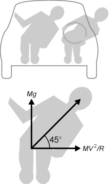
\[\begin{equation} V_{max} \quad = \quad \sqrt {\mu Rg} \end{equation}\]and the maximum cornering speed is reduced accordingly. Given a coefficient of friction around 1.0 on a dry road surface, the tyres can generate a centripetal acceleration no greater than \(1 g\), roughly 10 ms\(^{-2}\). Even at this level, without arm rests or doors to provide lateral support, passengers would have to lean sideways at an angle of 45\(^\circ\) to maintain a dignified equilibrium (figure 3). Perhaps that is why in everyday driving, lateral acceleration rarely exceeds \(0.3 g\).
Figure 3

Transients
So far we have only considered ‘steady state’ processes in which the vehicle travels on a curve of constant radius, or alternatively in a straight line. But what happens when the road switches between the two? Or changes from one radius to another? In practice, a car cannot be made to accomplish the transition between a straight road and a bend of any given radius instantaneously. A whole chain of events must take place, which has been summed up [2] as follows:
- The driver turns the handwheel, applying slip angle at the front wheels.
- After a delay associated with the front tyre relaxation length (see section C1717), the front wheels produce a side force which accelerates the nose towards the inside of the curve so the car begins to yaw.
- The body yaws, and as it does so, the rear axle is turned at an angle to its original direction of motion, which in turn creates a slip angle at the rear wheels.
- After a delay associated with the rear tyre acceleration length, the rear tyres start to develop side force too. Lateral acceleration increases, and yaw continues while yaw acceleration is reduced to zero.
- The car is now following a curve of fixed radius and yawing at a steady rate.
A more detailed analysis is beyond our scope, but it is worth pointing out that the transition has a marked effect on passengers. When we travel on board a vehicle, most of us can cope with quite large accelerations provided we have time to adjust our body posture. Then we can sense that the disturbance is building up and lean in the right direction. As explained in Section G0216, a steady level of acceleration is fine: it is the rate of change of acceleration that is the problem.
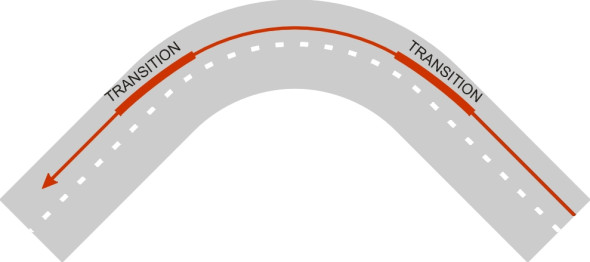
This is why highway engineers design new roads with ‘transition curves’ built into the road layout in which the curvature changes gradually. But existing roads, most of which follow an alignment that dates from the 19th century, are a different matter. There may be no transition curves at all, and the radius can vary abruptly in just a few metres. When moving from one section to the next, a driver cannot change the steering angle instantaneously however hard she yanks the handwheel, and even if that were possible, the car would take a moment to respond. So in practice, drivers create their own transition curves using whatever road width is available (figure 4).
Figure 4

Why a car spins when the rear wheels lock
Once in a few thousand miles, something happens that takes a driver by surprise. It might be a van pulling out unexpectedly from a side road. What should the driver do: swerve or brake? Both have their risks, but today, braking is safer than it was twenty years ago. ABS braking (the initials ABS come from the Bosch/Mercedes 1978 ‘Anti-Blockier System’) made cars more stable.
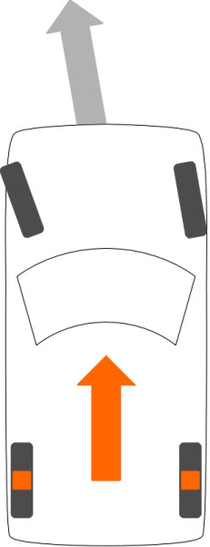
Before 1978, emergency braking often resulted in one or more wheels ‘locking up’. Instead of rotating, a locked wheel skids along the road, which is a liability for two reasons. First, it develops less friction, so there is less stopping power than the driver might expect. Second, the wheel no longer has a preferred path – for an object sliding across a level surface the frictional resistance is the same in all directions. It follows that if the front wheels lock, the driver loses the ability to turn the car: it will carry straight on whatever he or she does to the steering wheel. If the rear wheels are still rotating, they will at least keep the car pointing in the direction of travel so the occupants can see where they are going (figure 5).
Figure 5

On the other hand, if the the rear wheels lock, the front of the car will go where the front wheels are pointing. Unfortunately, if the front wheels are not pointing straight ahead, even if very slightly out of line they will deflect the front of the car to one side. But the rear wheels would go straight on, causing the tail to swing out of line (figure 6). At this point, the driver must act very quickly to regain control by releasing the brake pedal and applying a steering correction to counter the swing. This is quite difficult to do, not least because an emergency like this often happens when the driver is not expecting it, and the procedure may seem counterintuitive.
Figure 6

Let us suppose that the tail carries on swinging. As it does so, the whole vehicle rotates. The front wheels (which are still providing lateral guidance) no longer point in the original direction of motion, but off to one side, steering the car into an ever-sharpening curve. If the vehicle is travelling above a certain critical speed, around 20 km/h on a dry road with a coefficient of friction around unity [4], the spin is unstoppable (figure 7). Within a few moments, the car has rotated 180 degrees [3] and once more travels in a straight line, only backwards (figure 8). If you have ever experienced such an event, you won’t need to be reminded that it happens quickly, it is disorienting, and it is dangerous.
Figure 7

Figure 8

So you would expect the braking effort on a properly maintained road vehicle to be biased toward the front axle so that rear wheel lock-up is unlikely. Of course, the correct balance varies with road conditions so that any given set-up must be a compromise (see Section C0816). However the problem has been circumvented for passenger cars with the development of ABS, which makes a spin virtually impossible unless of course you apply the handbrake, which operates only on the rear wheels. Deliberate locking of the rear wheels will flip a car round to face in the opposite direction, a manoeuvre that explains the curious skidmarks you sometimes find on suburban roads, where night-time joyriders practise their ‘hand-brake turns’.
Acknowledgement
Photo on opening page of saloon car racing at Brands Hatch by Tom Wright