C.0414
Roll
If you ride a motorcycle, you will know what it means to heel the machine over. You do it every time you approach a curve, and if you get it wrong you can easily run off the road. Aircraft and speedboats also heel or ‘bank’ during a turn as do some passenger trains, but cars don’t. In fact, most road vehicles lean slightly outwards, a phenomenon called roll. It’s not intentional, but rather a side-effect of the way they are built. In fact, from the passenger’s point of view, roll is a nuisance because it adds to the discomfort caused by centripetal force. We slide laterally in our seats away from the centre of the curve, and when the vehicle rolls the seat is tilted so we slide downwards as well: gravity joins in (figure 1).
So why does a vehicle roll? An obvious answer is that the springs are elastic, and centripetal force acting on the vehicle makes it rotate, squashing the outside springs and stretching the inner ones relative to their normal positions. In this Section we will see that the degree of roll depends not just on the spring stiffness but on the geometry of the linkages, and in particular, it is the geometry that determines the instantaneous centre around which the body rotates.
Figure 1
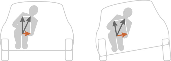
The roll centre concept
We stress the word ‘instantaneous’ because on most cars, when the body rotates the roll centre doesn’t stay in a fixed position for very long. Strictly speaking, it is the point about which rotation begins when starting with the body in an upright position. The idea of an instantaneous centre is used in many branches of engineering, for example, in the set-up of a tilting train (see Section R0410). For a road vehicle, the roll centre is determined by the suspension geometry, and in turn the roll centre determines the leverage that the centrifugal force can exert on the springs. To see why, we shall view the front and rear suspension separately, then combine the results later.
Roll centre definitions
There are several definitions of the roll centre, variously discussed in [5] [6] [13], but we shall mention only two:
- The ‘force’ definition: the point on the vehicle’s central plane of symmetry at which a lateral force on the body produces no roll.
- The ‘kinematic’ definition: the point about which the body can roll when considered as a mechanism.
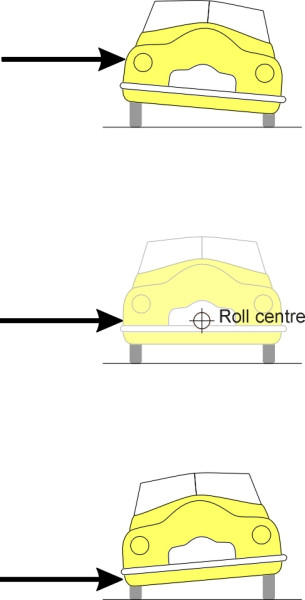
These two definitions say the same thing but in different languages. The first definition is the one preferred by the US Society of Automobile Engineers. To see how it works, you will need a workshop and a spare car. First, slice the car across the middle so you can deal with the front suspension and the rear suspension separately. Now prop up the front ‘half car’ and try to push it sideways with a hydraulic ram close to the front axle centreline. The ram bears on the car body at a certain height above the ground, as shown in figure 2. If the ram is too high up, the body will deflect appreciably, with the roof leaning away from the ram. If it is too low down, the body will again deflect, but this time it is the lower body that gives way, with the roof leaning towards the ram. In between, there will be a position at which there is no sideways movement at all and the body stays upright. The roll centre is located on the car’s longitudinal axis at this height. Of course, you can simulate this experiment on a computer, and that’s what engineers do when they design a new model.
Figure 2
Now let’s try the kinematic definition. The idea is to treat the suspension and car body as a mechanism in which each tyre is joined to the road by a pivot at the centre of its contact patch. When the mechanism flexes, almost every part of the body begins to move away from its initial position. We seek the one point that remains stationary, and this is the roll centre (figure 3). This alternative definition appears in many textbooks because although it glosses over some important details you can use it to find out roughly where the roll centre lies using only pencil and paper.
Figure 3
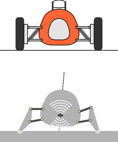
How to find the roll centre
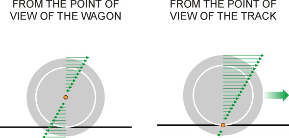
In fact, the body isn’t the only part of the car that rotates. The body is really just one link in a chain of suspension links, and each link ‘rolls’ about its own centre of rotation. Each of these centres is defined in exactly the same way as the body roll centre, but to distinguish them from the body roll centre we’ll just call them Instantaneous Centres (ICs). We can find the body roll centre by locating the ICs of the suspension links one by one, starting from the ground and working upwards along the chain until we reach the body itself. But we have to be careful because the IC of any given object depends on one’s point of view. Picture, for example, a railway wagon rolling along a track. If you are riding aboard the wagon, every part of the wheel seems to be moving except its centre, so the axle centreline is the IC from your point of view. If you are standing by the railway track, the axle is moving so the IC must be somewhere else. It lies at the centre of the contact patch, this being the only part of the wheel not in motion from your point of view (figure 4).
Figure 4
So, when considering a mechanism we must take each component in turn and work out its IC with respect to each of the others. This is easy for links that are connected directly through a pivot. Number the links 1 and 2. From the point of view of link 1, link 2 rotates around the pivot so this is where the instantaneous centre for link 2 lies. Similarly for link 2: the instantaneous centre around which link 1 rotates is again the pivot. The trick is to consider sets of three links at a time, using a simple theorem to bridge across from link 1 to link 3.
The Aronhold-Kennedy theorem tells us that the ICs of three objects moving in a plane must lie on a straight line [6] [11]. The objects don’t have to be physically connected, but for our purposes it’s easier to think in terms of a linkage in which the constituent bars are joined at pivots or slides, so let’s start with the swing-axle suspension as shown in figure 5. This suspension was used at the rear axle on several passenger car models during the 1970s. On either side of the vehicle, the wheel and axle form a rigid unit that is linked to the engine driveline via a universal joint at the differential casing. Notice that in the case of any car suspension, the road itself is one of the components; you can think of it as a bar that is pivoted at the contact patch of each of the two wheels.
Figure 5
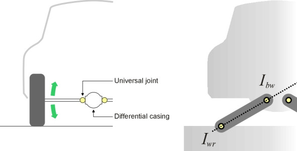
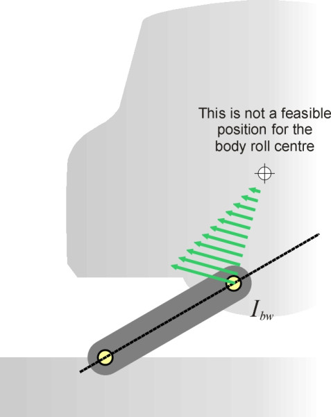
We begin with the road. It is usual to picture the left hand wheel-and-axle unit as pinned to the road at the tyre contact patch. So from the point of view of the road, this is the point about which the wheel-and-axle unit rotates, and therefore where its instantaneous centre lies. We label it \(I_{wr}\). Next comes the car body. It is pinned to the wheel-axle unit at the differential casing, and from the point of view of the wheel-axle unit, this is the point \(I_{bw}\) about which the body rotates. But what we want to know is the instantaneous centre \(I_{br}\) of the car body from the point of view of the road. This is where the Aronhold-Kennedy theorem comes in. It tells us that this third IC lies on the straight line drawn through the other two. It’s not difficult to see why. Figure 6 shows the body rotating about a point not on the line. The arrows represent movement relative to the road. Movement diminishes as we get closer to the roll centre, where it finally becomes zero. Now look at the arrow that passes through \(I_{bw}\). It has a component at right-angles to the dashed line, which is permissible because the universal joint is free to move circumferentially around the pivot at the tyre contact patch. But it also has a component in the radial direction, which is not permissible. If it were moving radially, the wheel-axle unit would have to stretch or contract. Since it forms a rigid unit, the motion of the body must be purely circumferential, which forces the instantaneous centre to lie on the dashed line.
Figure 6
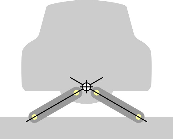
To finish the process, we must draw the other half of the suspension on the same diagram, as shown in figure 7. Now we have two lines, one for each half of the suspension, and the body roll centre we are seeking lies at the point where they cross.
Figure 7
Roll centres for some commonly used suspension types
Other kinds of suspension can be analysed in similar way, although the process may not be quite as straightforward. For example, in the case of the double-wishbone configuration, it’s necessary to combine some of the links to reduce the assembly to the ‘three link’ form. Let’s look at the left-hand side only (figure 8). Notice that the wheel and car body are joined not by a single member, but by two wishbones. However, the wishbones act as a single unit, and in the same way that we simplify the analysis of an electrical circuit by replacing parallel components with a single component, we need to to treat them as such. Starting at the wheel, we look across the upper wishbone (labelled U in figure 9). The pivot where this link is connected to the wheel is the IC for the upper link relative to the wheel, which we label \(I_{uw}\). At the far end, U is connected to the car body at a second pivot, which forms the IC for the body with respect to U, which we label \(I_{bu}\). From the Aronhold-Kennedy theorem we deduce that the body rotates relative to the wheel around an instantaneous centre located on the line through \(I_{uw}\) and \(I_{bu}\). If we repeat this analysis for the lower wishbone, we deduce that the body also rotates relative to the wheel around an instantaneous centre located on a second line, this time drawn through \(I_{lw}\) and \(I_{bl}\). Where the two lines cross represents the IC for the body relative to the wheel. We label it \(I_{bw}\).
Figure 8
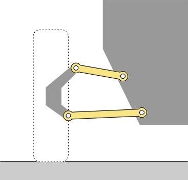
Figure 9
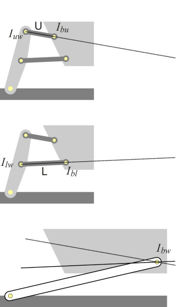
We have effectively replaced the wheel together with its two wishbones by a rigid wheel-axle unit pivoted on the car body at \(I_{bw}\). The problem is therefore reduced to a 3-link problem like the swinging link suspension we looked at earlier, and the body roll centre relative to the road must lie on a straight line through the contact patch and \(I_{bw}\). We repeat the analysis for the right-hand half of the suspension to produce another straight line (figure 10). Where the two lines cross is the body roll centre.
Figure 10
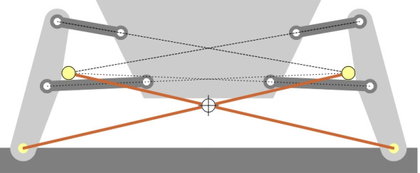
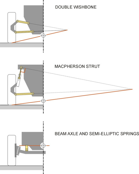
figure 11 shows the body roll centre (a) for the double wishbone suspension with corresponding roll centres for (b) the MacPherson strut suspension and (c) the rigid beam axle with semi-elliptic springs for comparison. Notice that the roll centre for the the rigid beam axle is quite high up, level with the spring attachment points. For the MacPherson strut it is lower down. In the case of the double wishbone layout, the roll centre can be positioned at almost any height we wish, by altering the angles and lengths of the wishbones.
Figure 11
Why is the roll centre important?
On a modern car, the roll centre usually lies between the road surface and the axle centreline for both front and rear axles. A comprehensive review of the positions for different suspension types can be found in [8]. Typical heights above ground for independent suspensions other than trailing link have been quoted as 30 – 100 mm at the front and 60 – 130 mm at the rear [15]. But more extreme values are not uncommon. For example in the case of a well-known saloon manufactured a few years ago, the roll centre for its Macpherson strut front suspension was at road surface level (i.e., height zero), while in the case of a Japanese saloon with double wishbone front suspension it was 138 mm above the surface [12].
The load path concept
Not everyone is happy with the analysis we have described because having established its position, one can easily forget that the roll centre doesn’t stay there. It moves as soon as the body begins to rotate, because the link geometry changes. A similar caveat applies whenever a passenger gets in or out of the car, because any alteration to the static deflection will alter the angles of the suspension links. An alternative way to predict body roll is to analyse the load paths – the routes via which the loads find their way through the suspension to the road [1]. Rather than a mechanism, we think of the vehicle as a structure and see how it distorts under the grip of a lateral force.
Figure 12
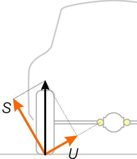
For example, in the case of the swing-axle suspension shown earlier, we can resolve the loads on either of the two wheels into two separate components as indicated by the right-angled triangle in figure 12. The component labelled \(S\) is directed at right angles to the link formed by the axle and wheel together as a rigid unit. This link can be pictured as a straight bar joining the two pivots labelled \(I_{wr}\) and \(I_{bw}\) as shown earlier in figure 5. The force component \(S\) contributes nothing to the axial load in the link and must be routed solely through the spring. By contrast, the force component \(U\) contributes nothing to the compressive load in the spring, but passes entirely through the bar. We say that component \(S\) follows the sprung load path through the vehicle springs and determines body roll, while component U passes through the unsprung load path, directly through the suspension links to their mounting points and does not affect body roll at all. Body motion can then be analysed directly in terms of compression and extension of the springs.
How the roll centre influences vehicle behaviour
Although the load path concept is the more rigorous of the two, we shall persevere with the kinematic roll centre concept because it helps one to understand what happens when a car travels round a curve. On a curve, the position of the roll centre - specifically its height above the road surface - is important because it affects three aspects of vehicle behaviour: (a) the amount of body roll, (b) handling, and (c) tyre wear.
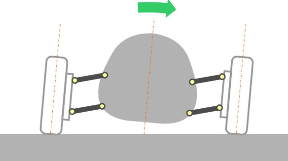
Let’s start with the angle of roll. If you think of the roll centre as an imaginary hinge between the sprung mass (car body) and unsprung masses (wheels and suspension), then other things being equal, the lower the roll centre, the greater the leverage exerted by the body mass owing to centrifugal force (figure 13). Hence a low roll centre means a greater roll angle. Too much roll is undesirable, because it is uncomfortable for passengers, and because with independent suspension, the wheels lean in the same direction as the body, and if the body leans outwards, the wheels do too (figure 14). It’s important to keep the wheels upright as far as possible, otherwise they are liable to lose grip (see Section C1717). In summary, a high roll centre is desirable both for passenger comfort and for roadholding (and in the unlikely event that the roll centre were above the centre of mass, the body would hang like a pendulum and the car would lean inward on curves, like a tilting train). Body roll is also critical for trucks, but for a different reason: when a truck is heavily loaded its centre of mass rises, and at a high roll angle it can move significantly away from its normal position, threatening to turn the vehicle over.
Figure 13
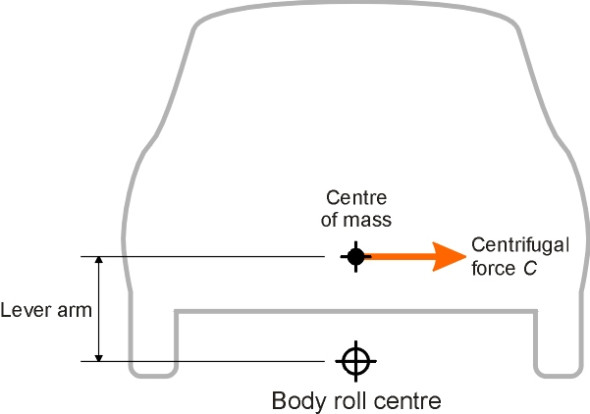
Figure 14
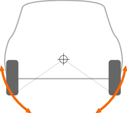
Unfortunately, a high roll centre means more tyre wear, because almost all cars today have independent front suspension. When the front axle bounces up and down over a bump, we have a new situation. The car does not roll, and instead of one wheel moving up and the other down relative to the body, both wheels rise and then fall simultaneously. The effect is shown in figure 15, where we reverse the normal situation and instead of allowing the body to move relative to the road we imagine the car held stationary, and make the road move up and down relative to the body. The arc followed by each contact patch is centred on the body roll centre, and with the body roll centre in the position shown, the wheels will scrub laterally across the road surface. The higher the roll centre, the greater the scrub and the greater the tyre wear, particularly at the front where the load is greater. On most cars, therefore, the height at the front is less than 150 mm [15]. In fact, if the roll centre is located exactly at the road surface the track width remains constant throughout [4].
Figure 15
Roll axis
At this point it seems we have two contradictory requirements: a high roll centre on the one hand is good for passenger comfort and roadholding, while on the other hand it is bad for tyre wear. But there is one more factor to consider: load transfer. To understand how load transfer works, we must combine the results of our roll centre analysis for the front and rear axles and consider the behaviour of the vehicle as a whole. The first step is to recognise that the two roll centres effectively create a hinge between the sprung and unsprung masses. The hinge rotates around the straight line joining the two centres, and because of the different linkages involved, the front axle roll centre is usually a little lower than the rear roll centre and the roll axis slopes upwards slightly from front to rear.
Roll stiffness
A car will travel round a curve only when forced to do so. It’s not in equilibrium, but accelerating sideways owing to a lateral force from the wheels, which drag the body to one side as they deviate from a straight path. The force is applied low down on the body shell, below the centre of mass, so the body rotates against the resistance of the springs. However, the process is easier to visualise if we replace the acceleration with a d’Alembert force. This is the familiar centrifugal force that appears to pull the car body sideways away from the centre of the curve, and thereby applies a torque around the roll axis. The greater the torque, the greater the rotation, and for small deflections we shall assume the relationship is linear.
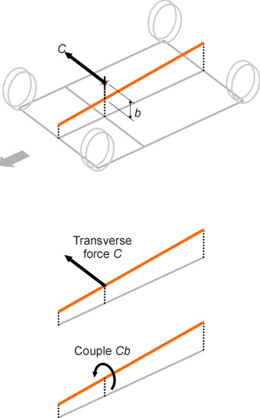
figure 16 shows the centre of mass in relation to the roll axis and wheels. The centrifugal force \(C\) acts at the centre of mass. Given a particular value of centrifugal force, the amount of roll therefore depends on two things, first, the height \(b\) of the centre of mass above the roll axis, and second, the stiffness of the springs. It is not difficult in principle, given the spring stiffness and dimensions for any given model of car, to work out the angles of roll for any given level of centrifugal force, but the calculations need to be arranged systematically and a computer spreadsheet helps.
Figure 16
We shan’t go into the matter here, but there are two special cases of interest. First, if the centre of mass lies below the roll axis, the body rolls in the opposite direction to the one we would normally expect, leaning inwards like a tilting train. Second, if it lies on the roll axis, there is no torque and zero roll. Although the passengers might like them, neither of these arrangements is used in practice because of the wheel scrub problem mentioned earlier, and perhaps because a small amount of body roll provides useful warning to the driver when the car is being pushed too hard and in danger of skidding off the road [9]. So how much roll is ‘normal’? Under a lateral acceleration of \(1g\), a few years ago one might expect a value of around \(5^\circ{}\) for a family saloon [2] [5]. But values seem to have fallen since then.
Load transfer in roll
When a vehicle undergoes acceleration, changes will occur in the vertical reactions between the wheels and the road surface, as if the load were being transferred from one pair of wheels to another (see section C2009). On a curve, the transfer takes place from the inside wheels to the outside wheels. Let us denote the centrifugal force acting on the car by \(C\). It acts through the centre of mass and its value is given by
(1)
\[\begin{equation} C \quad = \quad \frac{M V^2}{R} \end{equation}\]where \(M\) is the mass of the car, \(V\) is its speed, and \(R\) the radius of the curve. The overall load transfer between inside and outside wheels is fixed by the height \(h\) of the centre of mass above the road, regardless of the position of the roll axis or the stiffness of the springs. As shown in Section C2009, if the track width is \(w\), the extra load on the outside wheels is given by
(2)
\[\begin{equation} \delta P \quad = \quad Ch/w \end{equation}\]At the same time, the load on the inside wheels is reduced by a similar amount. But this load increment doesn’t have to be shared equally between front and rear. To tease out the relative proportions, we return to figure 16. Let the height of the centre of mass vertically above the roll axis be \(b\). Then the centrifugal force \(C\) can be pictured as two distinct components:
- A d’Alembert force equal to \(C\) acting at the roll axis,
- A d’Alembert couple about the roll axis equal to \(Cb\).
These two components are transferred to the ground in two different ways. The first, the primary ‘inertia’ component, is transferred through the suspension links (the unsprung load path) and while it results in a load transfer from inside to outside wheels, the transfer has no effect on the springs, so it is independent of spring stiffness. The load transfer at the front suspension is proportional to the height of the roll centre at the front, and the load transfer at the rear suspension proportional to the height of the roll centre at the rear. The second component is the ‘body roll’ component, which is directed solely through the springs (the sprung load path). The relative proportions carried by the front and rear suspension are controlled by the spring stiffness. If the front springs are stiffer, they will carry the greater share (the calculations are more complicated to describe than they are to carry out: examples are given in [7] [9]). There are also components of load transfer associated with any bodily shift of the centre of mass, together with the load transfer associated purely with the unsprung mass. We shan’t pursue either here since they are relatively small, so we are left with two distinct ways to change the distribution of load transfer between front and rear: (a) change the heights of the roll centres, and (b) change the stiffness of the springs.
Now, these two components can be manipulated independently to ensure that the overall load transfers front and rear are roughly equal during cornering [14]. Why is this a good idea? Because the friction force from a rubber tyre is not linear in wheel load: the gain in friction obtained by transferring load to the outside wheel doesn’t make up for the loss at the inside wheel (see Section C2009), and while load transfers can’t be avoided, if the percentage values front and rear are equal the overall loss of grip is minimised. The worst case occurs when the value at the rear is greater than the value at the front, because any loss of grip at the rear encourages oversteer (see Section C0418). Cars with independent front suspension usually have an anti-roll bar fitted (see Section C1114), which helps by stiffening the front suspension in roll and biasing the load transfer in the direction we want.
Conclusion
We have seen broadly how the height of each roll centre and the stiffness of the springs affect three aspects of vehicle behaviour: body roll, handling (the degree of load transfer and hence tyre grip on corners), and tyre wear. What we can’t do is prescribe an ideal arrangement. It depends what the designer wants to achieve, and in any case there are several different ways to adjust the parameters to achieve more-or-less the same outcome.
Moreover, our analysis doesn’t tell the whole story. The roll centre is determined by the suspension geometry, which changes whenever the wheels are deflected relative to the suspension mountings. Such deflections occur whenever the body moves away from the vertical, so the equations don’t necessarily describe what happens during the more severe cornering manoeuvres. Deflections also occur in response to a change in payload; with a full complement of passengers and luggage the roll might be greater or less than predicted, and for the same reason it will change continually on bumpy road during jounce and rebound.
Worse, there is a contradiction in the way the suspension is pictured in, for example, figure 5. The body can roll from side to side, but the diagonal links prevent it from bouncing up and down. There is only one degree of freedom where there should be two. You can check this by applying the Chebyshev-Grübler formula, which specifies the number of inputs needed to drive a planar mechanism. It’s beyond our scope here, but the details can be found in [10]. The problem arises from the assumption that the tyres are firmly pivoted to the road at the centre of each contact patch. In reality, the tyre has lateral flexibility; moreover, when the vehicle moves along the road the wheel scrubs over an appreciable distance from side to side [3].
In order to represent subtle effects of this kind, engineers have developed software that embodies a detailed representation of all the chassis components, and takes account of any flexibility in the connections between them. The ghost of the vehicle sits, as it were, inside the computer where it can be driven over rough terrain, tested under extreme conditions, and modified until it behaves in a satisfactory way. To this extent at least, the modern car is a computer-generated artefact.