A.1610
Aircraft configuration
During the Second World War, the pace of development in aircraft technology accelerated to new heights, leading to machines that were more powerful and faster than ever before. But at the end of the war, the need for military aircraft declined, and several manufacturers switched to different fields or went out of business. Nevertheless, innovation continued. The turbojet opened new possibilities for civilian transport: by air, a journey across the North Atlantic in a jet airliner took only a few hours compared with several days by steamship. If anything, public interest in aircraft was growing, and as a child, I remember reading and re-reading popular books that explained why aircraft of different shapes and sizes looked that way. In this Section, we’ll try and explain how the aircraft has evolved into the typical forms we see today, and briefly consider future possibilities.
The shape of the aeroplane
It seems that although there are more aircraft in our skies than ever before, the number of distinct varieties has declined since 1950. It is possible that they have matured into certain basic forms that are known to work well, and the rising costs of research and development have focussed attention on specific areas with the potential for improvement. This may or may not be true, but it is still useful to examine how aircraft have evolved into the configurations we see commonly today. Here, we’ll focus on the sort of aircraft with which most of us are familiar: passenger airliners that we use increasingly for business and holiday travel.
Parts and functions
An aircraft is a working vehicle with parts and functions whose roles go well beyond the creation of aerodynamic lift and drag. At the simplest level, a non-military aircraft is a machine for carrying passengers and goods from place to place. For military aircraft there is a wider variety of purposes that usually involves the carrying of weapons. By contrast, light aircraft are used for recreation, or for carrying small numbers of passengers on shorter trips. Staying with the airliner, as shown in figure 1 we can visualise the different parts of the machine as divided into:
- Payload (passengers and/or goods)
- Fuselage
- Crew
- Wings
- Tail
- Engines
- Fuel
- Landing gear
- Controls and communications equipment
Figure 1
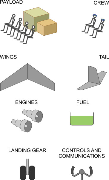
There is a natural dividing line between the payload and the remaining items in the list, which can be viewed as costs that the operator would want to minimise. Among them is the fuel, currently the source of much debate. Compared with land vehicles, the fuel carried by an aircraft accounts for a large proportion of the total weight, sometimes as much as a half at take-off, making it the largest single component apart from the aircraft structure itself. The wings and tail form a distinct group in that their purpose is to support the aircraft in the sky, and the shape of the wings is important not just from an aerodynamic point of view, but because it raises an interesting question in terms of structural design.
The load path to the atmosphere
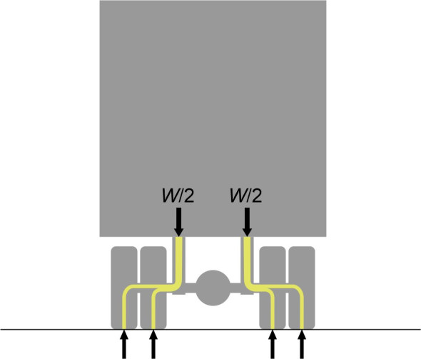
The earth’s gravitational field exerts a downward force on every object, so unless it’s falling freely, the object’s weight must be transferred to whatever it is standing on, and thence to the earth below. The wheels of a highway truck stand on the road that lies immediately underneath, so its weight is transmitted almost vertically in a straight line to the ground (figure 2).
Figure 2
Ships achieve an equivalent effect by transmitting their weight together with the weight of their cargo almost directly into the water through the hull surface. But aircraft gain support in a different way. In fact, there are two main differences between flying machines and other kinds of vehicle. First, the aircraft’s weight does not press downwards on the atmosphere, but rather, the atmosphere draws it upwards, mostly by suction. Second, by comparison with a land vehicle, the aircraft is structurally inefficient. Its weight is concentrated mostly within the fuselage, and passed to the surrounding atmosphere not directly, but spread out along the wings (figure 3).
Figure 3

In effect, the contact patch lies on the upper wing surface some distance away from the line of action of the load. It’s like a lorry whose wheels are mounted on very long axles cantilevered outwards on either side, which would need to be very strong axles to transmit the weight over such a distance. In fact, the wing is not an ideal shape for a cantilever. Essentially, it’s a thin plate, and as shown in figure 4, a bending load imposes high stresses within a beam of shallow cross-section - and the greater the wingspan, the greater the stress induced in the structural elements involved.
Figure 4
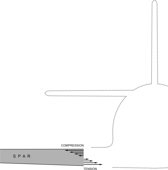
Figure 5
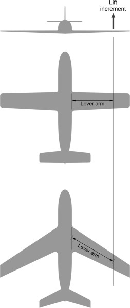
Also, if the wing is swept aft while the original span is maintained, the lever arm increases and with it, the stress (figure 5). Note that the stresses are highest at the wing root, and for this reason, the wings of most aircraft are thickest at this point. To summarise, if the lift force could be concentrated over a relatively small wingspan, the wings could be lighter, or less likely to fail under extreme loading conditions. Short, stubby wings are structurally more efficient.
Distributing the loads
But whatever their shape, the wings must supply whatever lift is needed to carry the aircraft’s weight. And we know that in subsonic flight, short wings generate more drag per unit of lift and slow the aircraft down - long thin wings are aerodynamically more efficient. It seems that structural considerations and aerodynamic considerations are fundamentally opposed. From a structural point of view, the best way to manage the components that make up the total weight of the aircraft is to spread them out along the wings, so that each is supported by the air flowing over the wing surface nearby. In this way, a weight placed near the wingtip, for example, does not cause a significant bending stress at the root. In practice however, not all these loads can be stacked at different points along the wings because first and foremost, the wing is an aerodynamic device. To travel fast and create the necessary lift with minimal drag, it needs to be thin. Hence the aeroplane has so far evolved along a different route. The only loads that are spread out along the wings are (a) the engines (each being housed in its own individual nacelle), and (b) the fuel. In an obvious sense, this means that most of the parts and functions, rather than being crowded into a single envelope, are separated from one another. This simplifies the whole creative process: design, development, testing construction, and maintenance.
Aerodynamic surfaces
At the beginning of the nineteenth century, the industrial revolution was gathering momentum. People began to think seriously about flying machines and how to build them. But no-one knew where to begin. What should an aircraft look like and how should it be propelled? The only examples to draw on were birds and insects with flapping wings. Then a young Englishman, George Cayley (1773-1857), took a radical step forward. He saw propulsion as a separate issue, put it aside, and experimented with model gliders instead. This enabled him to reduce aerodynamics to three distinct components: lift, drag, and stability. The outcome was a machine with three distinct parts: wings, fuselage and tail, each of which had a separate function that could be analysed independently. Eventually, his model glider of 1804 became the standard configuration for full-sized aircraft, one that has changed little over the last fifty years.
Figure 6
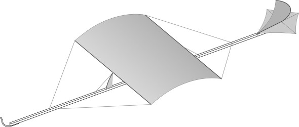
figure 6 is a sketch of a later model, which had cambered wings albeit of very low aspect ratio. Most aircraft today follow a similar pattern, with the wings mounted near the mid-point of the fuselage, and tail surfaces at the rear to stabilise the vehicle’s motion. Here, we’ll focus on the overall layout.
Wings
In straight and level flight, the lift force and the weight must be equal and opposite. Not surprisingly, therefore, the wings are fixed to the fuselage at a point close to the centre of mass. However, there remains the question of their vertical location on the fuselage side. In principle, they can be fixed anywhere between the bottom and the top, but certain positions are better than others. For a heavy aircraft, a low wing provides a convenient mounting point for the landing wheels, and it also makes the engines more accessible for maintenance on the ground. On the other hand, it raises the question of aerodynamic stability. Suppose that while flying straight and level, an aircraft is disturbed by a wind gust so it rolls anticlockwise, with the port wing falling and the starboard wing rising.
Figure 7
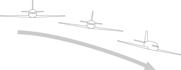
As shown in figure 7, it will slip downwards towards the port side. The phenomenon is known as sideslip, and if left unchecked the aircraft will also yaw to port, and the pilot must correct the motion to maintain the vehicle’s original course and speed. To make control easier for the pilot, the aircraft designer will try to configure the wings and fuselage so that when disturbed by a wind gust that rolls it to one side, the aircraft will return to a level position of its own accord. One way to achieve this is to raise the position of the wings. It is tempting to imagine that with a high wing, the fuselage suspended below will act like a pendulum to keep the machine upright, but the process is more complicated than that, and as we’ll see later in Section A0418, the key to roll stability lies in dihedral, in which the wings are angled upwards slightly, and which resolves the problem effectively even for aircraft with low-mounted wings.
Incidentally, for a heavy transport aircraft with cargo doors, a high wing position facilitates loading and unloading. For example, military transporters are often loaded from the rear, and with truck movements taking place around the service area, a high-wing layout keeps the engines clear of obstructions on the ground. For a light aircraft, a high wing makes access to the cabin easier for the pilot and passengers. It also reduces the ground effect when the aircraft comes in to land, so the pilot can apply the brakes more quickly after touch-down, which enables the machine to land within a shorter distance.
The canard
As an alternative to the conventional layout, the designer can exchange the positions of the wings and tailplane. The result is called a canard configuration. Here, the stabiliser together with the elevator control surface is located ahead of the wing as shown in figure 8.
Figure 8

Since the early days of flight, designers have been wary of the canard layout. If the mainplane stalls while the stabiliser is still generating lift, the nose will rise and make the stall worse, potentially pitching the aircraft out of control [5]. During the 1980s, however, the US light aircraft designer Burt Rutan maintained that a canard could not stall if the stabiliser were designed to stall first, in which case, the nose would fall so the vehicle would gain speed and recover. He went on to design several light aircraft that flew well and attracted a strong following in the USA. As it turned out, the canard has other advantages too: first, the control surfaces operate in undisturbed air, which presumably enables more positive control, preventing the downwash from the wings interfering with the stabiliser and elevators and making the aircraft difficult to handle. The second arises from the issue mentioned in Section A1810, that in a conventional layout, the tailplane is almost always fixed at a negative angle of attack to counter the tendency for cambered wings to pitch nose-down. In a canard layout, to achieve the same effect, the stabiliser must be fixed at a positive angle of attack so force is upwards rather than downwards, contributing to the lift instead of reducing it as in the case of a conventional tailplane. All these features were incorporated into the revolutionary Beech ‘Starship’ business aircraft, which was thought to be a major advance in light aircraft design. The production version first flew in 1989, but for various reasons, the machines did not perform as well as expected and only a few of those built were actually sold.
The flying wing
Another alternative is to remove the tailplane altogether. Designers have always wanted to do this. Assuming a tailless aircraft is stable, it should be lighter, it should generate less drag, and it should perform better than the equivalent conventional layout. This is not a straightforward exercise, because the horizontal part of the tail has three functions. The first function is to support the elevators, the moving surfaces that the pilot uses to change the pitch. The second function is to act as a counterbalance. As already mentioned, when launched into the air a cambered wing without a horizontal stabiliser will pitch nose-down. Consequently, during level flight the tailplane must be inclined at a negative angle of attack to produce a downforce. The resulting couple about the centre of mass balances the effect of the camber, and throughout the flight, relieves the pilot of the need to pull back continuously on the control column to stay on a level path. The third function has to do with stability in a turbulent atmosphere, with the tailplane acting like a weathercock to maintain a level course. We’ll return to this last function later: the point here is that if the outboard sections of a flying wing are swept aft as shown in figure 9 and inclined at a negative angle of attack – given ‘washout’ - they can be made to act in the same way as a tailplane.
Figure 9
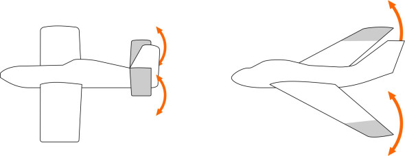
Several aircraft have been built on this pattern, but they’ve met with varying degrees of success because the outboard wing sections do not provide as much leverage as a conventional tailplane. I have a small collection of picture books featuring unusual aircraft of one kind or another, and among them are more than a dozen tailless machines built since the 1920s. They have all flown but none has been commercially successful or gone into extended military service. The most notable is the series of flying wing bombers built by Northrop in the USA. They were stable and flew at an impressive speed, and although not adopted by the US Air Force, they would presumably have been effective in action. Others were prototypes that for one reason or another did not achieve their potential. A tragic example occurred during the 1950s when aircraft manufacturers were competing to break the sound barrier. One of the contenders was the de Havilland DH-108, basically a Vampire fighter with the wings swept back and the tail removed; it suffered from pitching oscillations, and broke up over the Thames Estuary during a practice flight for a world speed record attempt [3].
For success, we must look elsewhere. During this period, a different tailless configuration, the delta wing, was discovered to behave in a more predictable way and was easier to handle. We have already mentioned delta-winged aircraft in Section A1610. The extended wing surface aft of the leading edge provides additional stability, and there have been many successful aircraft built to this pattern. Most are military aircraft, including fighters and large bombers. The delta planform allows a much higher angle of sweep and reduces the bending loads that otherwise occur in a conventional swept wing. Notably, the Concorde airliner had a delta planform with a very high angle of sweep in which the leading edge followed an ogive curve.
The tail
The role of the tail as conceived in Cayley’s layout is to stabilise the direction of motion of the aircraft in flight, and to provide a means of control. We’ll be dealing with both these aspects later in Sections A0418 and A0415, but it’s worth mentioning here how the fixed elements (the horizontal tailplane and the vertical fin) do their job, because this determines where they need to be fixed to the fuselage. Both work in the same way, acting like a weathercock when the aircraft is disturbed by a turbulent gust of air. The fin provides directional stability, keeping the aircraft on a steady course. The role of the tailplane is to provide longitudinal stability, which refers to pitching motions in the vertical plane through the aircraft’s central axis, and we’ll say a little more about it because it involves another factor as well. Longitudinal stability – or lack of it - arises from the relationship between the tailplane and the wings. Imagine the aircraft in steady, level flight. If disturbed by a wind gust or temporary loss of control, we want the aircraft to return automatically towards its initial position.
Figure 10

In figure 10, we see the aircraft pitched nose-up, and like a weathercock, the tailplane makes it pitch downwards again. Being at a high angle of attack, it exerts an upward force, and although the restoring force may be small, it is acting on a long lever arm relative to the centre of mass, exerting a torque on the aircraft that tends to rotate it back towards the horizontal position. The same happens in reverse when the nose pitches down: the tailplane exerts a couple acting in the opposite direction.
Of necessity, the tail of a conventional aircraft operates in the wake of the fuselage and wings. Whether or not it works effectively depends among other things on its vertical location. At one time, it was common practice to fix the tailplane to the rear end of the fuselage either a little below or a little above the level of the wings. Things changed with the arrival of jet airliners whose engines were mounted at the rear (figure 11).
Figure 11

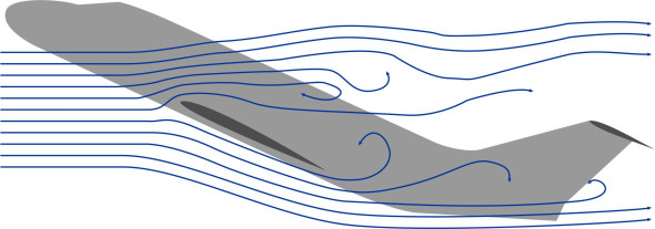
To keep it clear of the exhaust, the tailplane was move to a higher position on the fin, and subsequently, in many cases mounted on top, a configuration known as the ‘T-tail’. This configuration has continued in use on many aircraft to the present day. It improves the aerodynamic effectiveness of the fin because the tailplane acts as an endplate and prevents air from leaking over the top, in the same way that winglets discourage air from leaking between the lower and upper surfaces of the wings. And by sweeping the fin rearwards, the designer can position the tailplane and elevators further aft than would otherwise be the case, which increases their lever arm and enables more positive pitch control. However, the T-tail doesn’t work well if the aircraft goes into a deep stall. As shown in figure 12, under these conditions the nose is pitched at a very high angle of attack and the wings generate eddies that blanket the tail so the moving surfaces lose their effectiveness and the pilot cannot regain control [8].
Figure 12
Fuselage
For most aircraft, the various parts are linked together via the fuselage, a distinct structure that has no aerodynamic function but carries the crew and the payload. It’s true that designers once considered carrying passengers inside the wings, but this turned out to be more difficult than expected. During the 1920s, the G-38 built by German manufacturer Junkers went part of the way towards this goal. In addition to the regular fuselage accommodation, two small cabins were located in the wing roots near the aircraft centreline, which were 1.7 metres deep. Windscreens at the leading edge enabled passengers to see ahead [6]. A few other manufacturers took up the idea, but to my knowledge it hasn’t been tried since. The reasons are straightforward. Today, aircraft fly much faster, so the wings must be thin, and the aircraft must operate at a high altitude where the air density is less dense and the pressure far below the value needed to sustain life. Hence the cabin must be pressurised, which adds greatly to the stresses in the cabin walls. The lightest and most efficient structure for resisting internal pressure is a cylindrical tube.
Fuselage configuration
Hence, the fuselage of a modern transport aircraft is a tube aligned parallel to the direction of motion, streamlined at the front and rear, and with the stern cut away underneath to prevent it scraping on the runway during take-off. This doesn’t rule out the possibility of two tubes arranged in V-formation as described earlier in Section A1610, but this hasn’t yet materialised. A cylindrical tube has constant cross-section and is structurally simple: it can be built to whatever length is needed for the aircraft under consideration. As well as being able to resist internal pressure, it has the advantage over other shapes of constant cross-section that it has the least surface area and hence the least possible friction drag when aligned in the direction of the air flow. To optimise payload capacity, however, the designer may prefer an oval profile. This will introduce bending stresses into the fuselage walls, but they can be avoided by blending together two or more cylinders as shown in the ‘double bubble’ layout of figure 13. The horizontal floor/ceiling panel acts as a bracing member.
Figure 13

On many airline flights, the passengers and luggage amount to a relatively small proportion – about 20% - of the total weight if one includes ancillary supplies such as food and water. On the other hand, passengers occupy a significant volume, and it’s the space requirements that determine the fuselage diameter for most aircraft. The pressure inside is not maintained at a constant value but varies during each flight under the control of the cabin ventilation system. At take-off, it is set to the same value as the atmospheric pressure outside. But as the aircraft climbs the external pressure falls, ultimately to a value about one fifth of the value at sea level. Hence there is a large pressure difference across the fuselage skin, which inflates like the skin of a balloon and undergoes considerable tensile stress, but when viewed in cross-section, there are no bending stresses in the walls. To reduce the pressure difference, as the aircraft gains altitude, the cabin ventilation system reduces the internal pressure gradually to a value somewhat below atmospheric pressure on the ground. The minimum allowable cabin pressure as specified in US regulations is 75 kPa [7] compared with 101 kPa at sea level.
An alternative to the regular fuselage configuration is the twin-boom layout, in which the fuselage is shorter than usual, and the tail is carried on two booms extending rearward either directly from the wings or from the engine nacelles. Few aircraft of this configuration are flying today, but in the past, there were many notable examples such as the Lockheed P-38 ‘Lightning’ (figure 14), the De Havilland Vampire jet fighter, the Fairchild C-119 ‘Flying boxcar’ cargo carrier, and the Rutan Voyager.
Figure 14
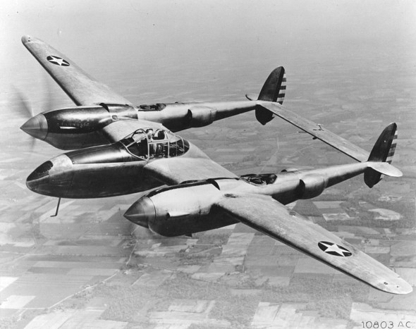
The Vampire was one of the first jet fighters, and the designers wanted to keep the intake and exhaust ducts as short as possible to minimise friction. Mounting the engine in a relatively short and squat central pod enabled it to deliver greater thrust. The Flying Boxcar and its predecessor the Fairchild Packet were commissioned as military troop carriers with rear-mounted doors to facilitate loading. The Rutan Model 76 Voyager was an experimental machine: the first aircraft to fly around the world without stopping or refuelling. It was designed by Burt Rutan with two engines located within the central pod, one at the front and one at the rear, and a canard tailplane mounted on the twin booms that extended forward of the wings.
Doors and windows
People often wonder why the windows of a passenger aircraft are so small. The reason is that at cruising altitude, there is a net pressure difference of roughly 50 kPa between the inside and the outside of the fuselage that tends to push them out. Aircraft windows vary greatly in size from one model to another, but assuming an area of 1 000 cm\({}^{2}\), the result is an outward force on the window of about half a tonne. A similar calculation for a typical aircraft door suggests an outward force of about 10 tonnes. Given the dire consequences of a failure, a great deal of care goes into its design and construction. Surprisingly, although the doors open outwards (they must, in order to facilitate emergency evacuation) each door is slightly larger than the opening in which its sits. In effect, it acts as a plug with tapered sides so the internal air pressure holds it firmly against the seal: it can’t spring open in mid-flight. The hinge is an elaborate mechanism that comes into play when the aircraft is on the ground and the pressure difference vanishes. It enables the door to tilt and slip through the opening at an angle.
The width of the opening is critical. Earlier generations of airliners had relatively narrow doorways, and it was discovered that in an emergency evacuation, passengers could become jammed in the hurry to get out. This was solved by a relatively modest increase in door width, and since that time, all aircraft manufacturers must demonstrate to the licensing authorities that when loaded to its maximum capacity, all passengers can be evacuated within90 seconds using just half of the exits.This requires doors at intervals around the fuselage. On the A380 for example, there are 16 emergency exit doors, only three of which are used for normal boarding and disembarkation.
Engines
The engines are the heaviest and most complicated parts of a flying machine. They disturb the surrounding atmosphere, drawing air towards them and expelling it behind in a concentrated stream. The problem for the designer is how to integrate them into the structural framework so they operate efficiently without comprising the aerodynamics of the wings and tail. It’s a question that must be decided at an early stage in the development process, because once decided, it’s hard to change and it will affect many aspects of the aircraft’s performance.
Propeller-driven aircraft
Aircraft today fall into two main categories: propeller-driven machines, and machines powered by some form of turbojet. Together with short-haul airliners, most light aircraft are propeller-driven. As discussed earlier in Section F1518, at low speeds a propeller is more efficient than a turbojet because of its large diameter. It draws in a great deal more air per second but accelerates the air parcels through a relatively small speed increment. This means that for any given level of thrust, the energy wasted in the slipstream is less than the energy wasted by a turbojet, which acts on a relatively small mass of gas but expels it at very high speed from the exhaust nozzle. However, the engine that drives the propeller is a different matter. A piston engine burns fuel that contains a great deal of chemical energy, but it converts only a small proportion of that energy into useful output [4]. Moreover, piston engines are not as reliable as turbojets. This is why ‘turboprop’ engines became popular for medium-range passenger aircraft during the 1950s and remained so for some while. A turboprop is a hybrid configuration in which the power source is a turbo jet: the propeller is mounted on a shaft that extends forward of the engine casing. In its heyday, the turboprop worked well, but eventually it gave way to the fanjet, a different form of hybrid that we’ll describe shortly.
In principle, a propeller can be mounted either in front of or behind the engine. A machine with forward-facing propellers is said to have a ‘tractor’ layout, while a machine with aft-facing propellers is termed a ‘pusher’. Some have both. In the early days of flight, many aircraft were canards, for which the pusher configuration was the natural choice. But as aircraft became more powerful and evolved into military weapons, the canard layout lost favour because pilots who bailed out in combat could be injured by the rear-mounted propeller. Moreover, a pusher propeller operated in the disturbed wake of the fuselage and wings, so the velocity of the air interacting with the propeller blades varied from point to point on their orbit round the propeller disk. This created vibration and reduced the propeller’s efficiency (the results of extensive wind-tunnel tests can be found in [10], which in comparison with typical results for a tractor propeller suggest a reduction of 10%). This did not prevent a revival of interest during the 1980s in the pusher layout for light aircraft, and some survive today.
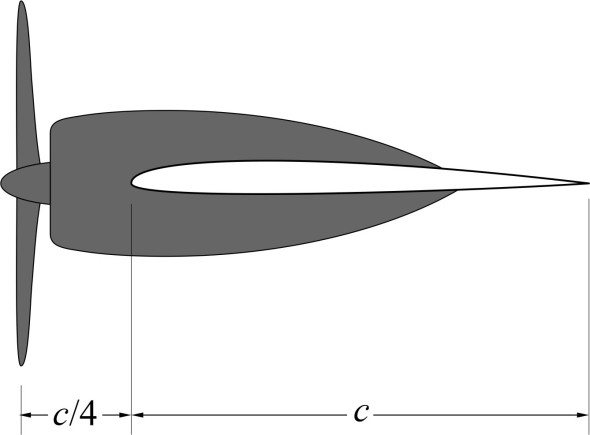
Returning to the more common tractor layout, we find that on a large aircraft, the engines and propellers are best spaced out at intervals along the wings. During the 1930s, NASA tests showed that the optimum location is level with the wing centreline as shown in figure 15, with the propeller disk positioned at a distance of \(c/4\) ahead of the leading edge, where \(c\) is the wing chord [1].
Figure 15
Jet engines
You’ll have noticed that almost all the jet engines that power commercial aircraft are housed not inside the wings or fuselage, but in separate nacelles either suspended from the wings or mounted on either side of the tail. They project outwards into the air stream, where the additional surface area of each nacelle generates interference drag, pressure drag and friction drag. This was not always so. The engines of early airliners such as the de Havilland Comet were ‘buried’ in the wing roots, while the engines of jet fighters were (and still are) integrated into the fuselage. Yet in 1947, Boeing opted the nacelle system for its B-47 Stratojet bomber. As was standard with propeller-driven aircraft, the engines were spread out along the wings, but not level with the leading edge; instead, they were slung beneath on short struts or pylons.
Figure 16
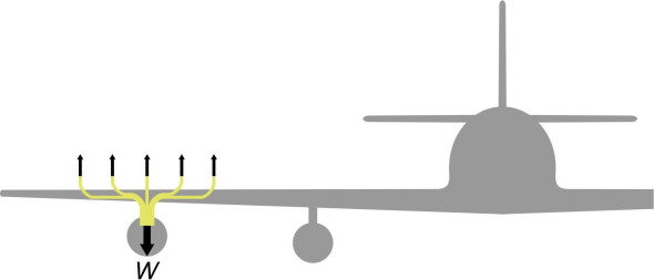
The same layout was adopted for the 707 and the 747 civil airliners. It has several advantages. First, as shown in figure 16 the weight of each engine is transmitted almost directly to the air flowing over the wing surface above so it doesn’t exert a large bending moment on the wing spars, which can be lighter as a result. Second, engines mounted on pylons are easier to maintain: while the aircraft is waiting at an airport terminal, the ground staff can carry out checks and if necessary, fix problems more quickly than would otherwise be possible. The pylon mountings also keep the engines separate from the wing spars, which means that the wing is less likely to fail in the event of an engine fire. The engines do not lie directly underneath the wings, but project forward beyond the leading edge (figure 17), which reduces the aerodynamic interference between the nacelle and the wing while permitting a smaller vertical gap between them and hence a greater ground clearance below.
Figure 17

Ground clearance became an important issue with the arrival of the ‘fanjet’ engine, whose overall diameter is larger that of a turbojet. Put simply, one can picture a fanjet as a development of the turboprop. Like a turboprop, it is powered by a jet engine, but instead of a traditional propeller, it carries a large fan that acts both as a propeller and a compressor that feeds air into the turbojet intake immediately behind. The fan is enclosed within a duct that optimises the air flow and reduces noise. Most of the thrust comes from the fan rather than the engine exhaust. Today, most commercial aircraft are powered by fanjet engines, which enable them to fly higher and faster than a propeller-driven machine, and more economically than a ‘pure’ turbojet.
For smaller commercial aircaft, as an alternative to suspending them from the wings, jet engines can be mounted on either side of the fuselage near the tail. The first airliner with rear-mounted engines was the 1955 Sud-Aviation Caravelle, pictured earlier in figure 11. This configuration enables the fuselage to sit closer to the runway when stationary on the ground, and therefore permits a shorter undercarriage. It also eliminates aerodynamic interference between the engines and the wings, and makes the aircraft easier to control if one of the engines fails. On the other hand, rear-mounted engines change the balance of the machine, because the centre of mass moves aft and relative to the fuselage, all the aerodynamic surfaces move aft as well, so that the tail unit projects well behind the rear extremity of the fuselage and a heavier fin is needed to support the tailplane. You’ll find these issues discussed in more detail in, for example, [9].
Looking ahead
Cayley’s vision of a flying machine with the wings and tail attached to the fuselage set a pattern that has been followed by transport aircraft ever since. There have been a few variations such as the canard and the delta, and one that we have not mentioned so far: the swing-wing concept that emerged during the 1960s in the form of the General Dynamics F-111 and the Panavia Tornado fighter planes. They could fly at supersonic speeds with the wings swept aft, yet take-off and land safely with the wings extended almost at right-angles to the fuselage. Other swing-wing aircraft have been proposed, notably the Boeing supersonic airliner that was conceived at about the same time as Concorde, but the proposed hinge mechanism turned out to be impractical, so the idea was ruled out of contention and the project abandoned. On the other hand, flying wings have continued to stir the designer’s imagination. It is conceivable that with the aid of computer simulation and AI, there will emerge a configuration in which every part of the aircraft surface contributes to lift, and the enclosed volume can be used to house passengers and cargo. If the engines are mounted in the slow-moving boundary layer over the trailing edge, it is theoretically possible to take advantages of the wake ingestion principle used for high-speed power boats as described in Section M1405. This would reduce fuel consumption because there is less energy lost in the exhaust [2]. At this point, we’ll leave the question of aircraft configuration behind, and in the Sections that follow, turn our attention to the way an aircraft is handled and how it behaves in normal service.