A.1410
High speed aircraft
‘Air-breathing hypersonic flight is … the last frontier of vehicle design’
During the last century, propeller-driven aircraft reached a peak. As the air forces of different nations fought each other during the Second World War, single-seat fighters achieved speeds in the region of 700 km/h (450 mph). But there seemed to be a limit on how fast they could travel, for reasons. First, the propeller blades provided limited thrust. Second, pilots discovered that although they could reach high speeds in a dive, the aircraft became difficult if not impossible to control. Both phenomena were connected with the speed of sound in air. It had long been known that streamlined objects such as bullets and shells could travel faster than sound when fired from a gun: in the early 1700s, English scientist Benjamin Robins (1707-1751) carried out experiments to measure their speed by firing them at a ‘ballistic pendulum’ [8]. But an aircraft that could travel at supersonic speed under human control was a different matter. It was only with the arrival of the jet engine, which produced consistently high thrust in the transonic regime, that manufacturers could set about developing a suitable air frame whose aerodynamics could cope with the shock waves that interfered with the control surfaces. It became a race between competing nations to ‘break the sound barrier’, a story that was taken up by the press and caught the public imagination. There were casualties, but today we know more about the forces involved and how to control them, so we’re accustomed to the notion of military aircraft flying at speeds well above the speed of sound, together with re-entry capsules that carry astronauts returning to earth through the atmosphere at speeds many times faster.
Wings
The aerodynamics of high-speed flight is a subject in its own right. We covered some of the essentials in the preceding Section (A1615), and you may want to refer to it from time to time. Among other issues, we pointed out the distinction between three speed regimes: subsonic, in which the air flow everywhere around the machine moves at less than the speed of sound, supersonic, in which the air flow moves everywhere faster than the speed of sound, and transonic, where the flow pattern effectively is a mixture of the two. Almost all practical aircraft come into the first category. Nowadays, supersonic air flow is limited to rockets, missiles and space vehicles returning to the earth’s atmosphere. Aerodynamic behaviour in the transonic regime tends to be unpredictable, and aircraft spend as little time as possible flying within this range.
Figure 1
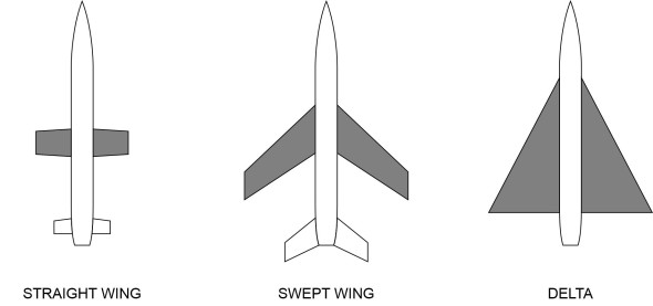
So let’s start by looking at the wings. The main alternatives for a high-speed aircraft are shown in figure 1. They are
- straight wings
- swept wings
- a delta wing.
Straight wings
We know from basic flow theory that for an aircraft flying at modest speed, long, straight wings provide high lift with relatively little drag. They’re efficient. Aircraft built on this pattern form the bulk of smaller flying machines. They include privately owned craft together with smaller airliners that provide feeder services for intercontinental routes. Their speed is limited by the drag divergence that occurs with all conventional aerofoils on the approach to the transonic regime, together with oscillating shock waves over the wings.
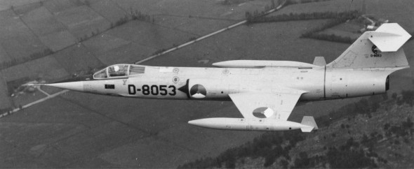
Straight wings are also used for a very different category of flying machine: rockets, missiles, and very high speed aircraft that operate within a supersonic flow field. Here, a short, straight wing has certain advantages. It is light in weight but rigid, and because of its small area, it doesn’t produce much wave drag at supersonic speeds. Given a thin profile with sharp leading and trailing edges, at a low angle of attack it behaves mostly like a flat plate). Now, the coefficient of wave drag \(C_{D,W}\) for a finite, flat-plate wing has been expressed in the following form [1]:
(1)
\[\begin{equation} C_{D,W} \; =\; \frac{4\alpha ^{2} }{\sqrt{{\rm Ma}^{2} -1} } \left(1-\frac{1}{2R} \right) \end{equation}\]where Ma is the aircraft speed expressed in Mach number form (\(V\) divided by the speed of sound), the dimensionless parameter \(R\) is equal to \({\rm AR}\sqrt{{\rm Ma}^{2} -1}\), and AR is the aspect ratio. The formula tells us that the wave drag coefficient falls dramatically for short, stubby wings of low aspect ratio, the opposite of what happens with subsonic wings. During the early days of supersonic flight, wings of this type seemed an attraction option for fighter aircraft whose role was to get into the air and intercept enemy bombers as fast as possible. They were chosen for the Lockheed F-104 fighter (figure 2), the first such aircraft designed for sustained flight at Mach 2. It was built originally for the US air force. The wing was machined from a billet of solid material to a bi-convex section profile with aspect ratio of only 2.45, a thickness-chord ratio 0.0336, and a razor-sharp leading edge. It didn’t produce much lift at low speeds, and several pilots lost their lives in accidents during take-off and landing [16].
Figure 2
Swept wings
Today, most high-speed aircraft have swept wings. By changing the angle that the wing makes with the fuselage when viewed in plan, it is possible to transform the air flow and reduce the drag. To understand how, imagine a straight wing being pivoted around its root through an angle \(\Lambda\) as shown in figure 3 (the symbol \(\Lambda\) is the Greek capital lambda).
Figure 3

The wing area remains the same, but the span falls, and at every point along the wingspan, the chord increases by the factor \(1/{\rm cos}\left(\Lambda \right)\). The pay-off lies in the interaction between the air parcels and the wing surface. It changes, because the lift and drag depend on how fast they are travelling not in the direction of the oncoming flow, but perpendicular to the leading edge. In effect, the velocity of each particle is split into two components as shown in figure 4. The component parallel to the leading edge plays no part: an air parcel travelling in this direction does not interact aerodynamically with the wing surface at all.
Figure 4
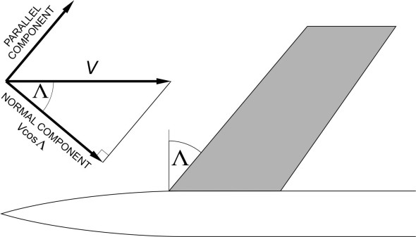
As shown in the Figure, the component normal to the leading edge is \({\rm Ma\; cos}\Lambda\). It follows that the aerodynamic forces acting on the wing are equal to the forces that would occur with the oncoming flow moving at velocity \({\rm Ma\; cos}\Lambda\) at right-angles to the leading edge. The air velocity is effectively reduced. This idea was first put forward by German aerodynamicist Adolf Busemann in 1935, but at the time, there were no jet engines, and a propeller-driven aircraft could not travel fast enough for a swept wing to be useful. But the situation changed towards the end of the Second World War, when German engineers succeeding in building high-speed jet aircraft with swept wings; soon after, the concept was taken up by military and civil aircraft companies throughout the world.
In practical terms, a swept wing enables an aircraft to travel faster before it encounters the drag divergence that acts as an upper limit to the possible range of cruising speeds for a conventional straight wing. Although the aircraft itself may be travelling at supersonic speed, the flow over the wing surface is effectively subsonic, with little or no wave drag. Hence the wing can be designed with a conventional aerofoil section: thicker, with a rounded leading edge, so it behaves better at low speeds as well. Suppose the target cruising speed is \({\rm Ma}_{target}\). Then the key requirement is that the normal component of this velocity is less than Mach 1.0. For the sake of argument, if we put the normal component equal to Mach 1.0, we see from figure 4 that
(2)
\[\begin{equation} {\rm Ma}_{target} .\cos \Lambda \; =\; 1.0 \end{equation}\]which corresponds to a sweepback angle of
(3)
\[\begin{equation} \Lambda \; \; =\; \; {\rm acos}\left(1/{\rm Ma}_{target} \right) \end{equation}\]For example, suppose we are designing an aircraft to cruise at Mach 2.0. Then equation 3 tells us that to avoid supersonic air flow over the wing surface, the sweepback angle must be greater than acos(1/2.0) or 60\({^\circ}\). In practice, swept wings have little advantage for aircraft flying at speeds greater than Mach 2.0 [9].
A swept wing can reduce drag, but it also has disadvantages. Because in effect, the air is flowing more slowly over the surface at right-angles to the leading edge, at any given aircraft speed and angle of attack, it generates less lift, and the slope of the lift curve falls. Crucially, the maximum lift coefficient is less, so the wing generates less lift at low speeds during take-off and landing [12]. In addition, the lift force is less evenly spread across the wingspan with a greater concentration at the wingtips, which increases the risk of a tip-stall. We’ll return to the dangers of tip-stalling in Section A0415, but for the moment, note that the problem can be corrected by dividing each wing into separate sections each having a different section profile. For a transport aircraft, the aim is around 5% reduction in the angle of attack at the wingtips - a 5% ‘washout’ [7].
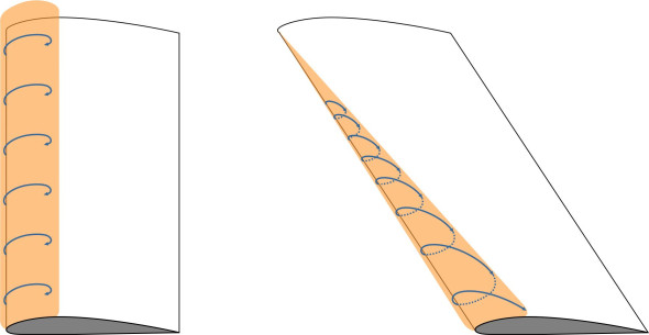
Finally, although the component of flow parallel to the leading edge does not interact directly with the wing surface, it leads to an interesting phenomenon when normal component separates over the leading edge when the aircraft is flying slowly with the wing at a high angle of attack as shown in figure 5. With a swept wing, the air parcels inside have an additional velocity component outboard, and follow a spiral path towards the wingtip (figure 6). This is a characteristic feature of the flow over a delta wing, which as we’ll now see, produces lift in a different way from a conventional wing.
Figure 5

Figure 6
The delta
Behind the trailing edge of a swept wing is a V-shaped gap or ‘notch’. The greater the angle of sweep, the smaller the notch, and if it’s small we might as well fill it in. The wing then becomes a delta, a triangular platform with a straight trailing edge from wingtip to wingtip. Given a sufficiently high angle of attack, a delta can provide enough lift for take-off and landing without flaps or slats, and structurally, the triangular planform is more efficient: the main spars can be rearranged at right-angles to the aircraft’s central axis so they are shorter and less highly stressed than is the case with a swept wing (figure 7).
Figure 7
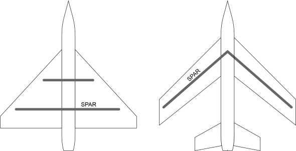
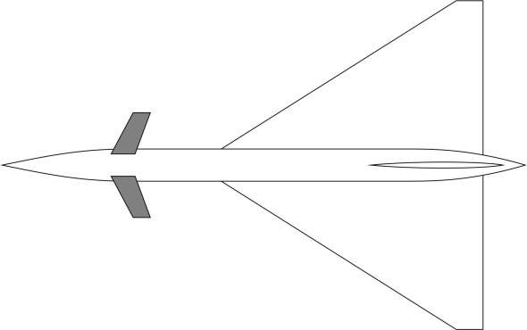
It was for reasons of this kind that the delta layout was adopted for several military aircraft during the 1950s and 60s. It then evolved into a new family of slender wings that were designed specifically for supersonic flight. With a very high angle of sweep, the flow pattern over the surface of a slender delta produces less drag [10]. At low speeds, much of the lift comes from the separation vortices over the leading edge. To encourage vortex separation, the leading edge is sharp. In addition, it follows an ogive shape in plan (figure 8). Other features are less obvious. They include a degree of camber and twist that make the wing look as if it is drooping slightly at the wingtip. Such features help to stabilise the vortex so it is maintained across a wide range of flying conditions, from take-off to cruising at Mach 2.0 and beyond.
Figure 8
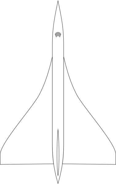
Figure 9

So how does the vortex create lift? A cross-section of the vortex structure is shown diagrammatically on the left-hand side of figure 9. The air flow separates over the leading edge, then returns to the wing surface before reversing direction to complete what appears in cross-section to be a circular orbit known as the primary vortex. In practice, the cross-section may be more complicated. When reversing along the wing surface, at the point marked ‘A’ in the diagram on the right-hand side, the air parcels meet an unfavourable pressure gradient and may separate again to produce a secondary vortex that rotates in the opposite direction. The air parcels near the core of a vortex travel very fast, much faster than those further away, and it’s here that the fluid pressure falls to a minimum.
Figure 10
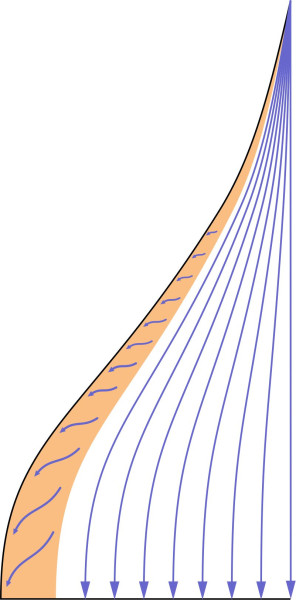
figure 10 is a plan view of the streamline pattern of the air parcels travelling close to the upper wing surface, with the zone of low pressure shaded in red. It shows how the vortex applies an upward suction force along the leading edge; when the aircraft is travelling slowly at a high angle of attack, the vortex accounts for a significant proportion of the total lift. At supersonic speeds, it becomes less important, since much of the lift is provided by the shock wave acting on the underside of the wing.
This layout was used successfully for the space shuttle as well as for the Concorde supersonic airliner, but is not used for transport aircraft today. The reason seems to be that the slender delta has practical disadvantages. First, when flying with its nose in the air during take-off or landing, the pilot cannot see the runway. In the case of the Concorde airliner, this problem was solved by mounting the nose cone on a hinge so it could be lowered to provide a better field of view (figure 11).
Figure 11
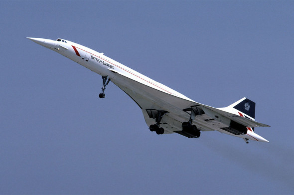
Second, with a slender delta, to make the aircraft climb, the pilot must pull back the control column. With a conventional aircraft, this raises the elevator surfaces on the tailplane, so the tailplane falls, the angle of attack rises, and almost immediately, the wings generate more lift. In the case of a delta wing, however, the elevators are mounted at the trailing edge of the wing itself, and when they rise, this momentarily changes the cross-section, effectively reducing the camber. Hence the lift falls, and the aircraft may lose height before it responds by pitching nose-up (you might like to compare this with the situation that arises when steering a ship away from an obstruction as described in Section M0505). This is why some delta aircraft have an additional control surface installed ahead of the wing in a ‘canard’ configuration (figure 12).
Figure 12
Third and last, a slender delta wing delivers a relatively low ratio of lift to drag, typically of the order of 7.5 at a speed of Mach 2.0. Hence it cannot carry a large payload. On a fully booked transatlantic flight, the Concorde burned nearly a tonne of fuel for every passenger on board. Partly for this reason, the aircraft did not deliver an economic rate of return, and having entered service in 1976, it was finally withdrawn in 2003.
Fuselage
Having looked at the wings, we can now turn to the fuselage. For most aircraft, it forms a distinct part of the vehicle structure that among other things, carries the payload. Afterwards, we’ll briefly consider aircraft whose wings and fuselage are not separate entities, but blended into a single whole.
Body shape
Typically, the fuselage is shaped like an elongated cylinder, tapered at either end to smooth the air flow and reduce resistance (figure 13). For high-speed flight, the length \(l\) and diameter \(d\) are important, and the ratio \(l/d\) is called the ‘fineness ratio’.
Figure 13

For conventional aircraft, it is typically in the region of 8:1, but for high-performance aircraft it may be much higher because at supersonic speeds, a long, narrow cylinder produces less wave drag than a short, fat one. Also, the drag can be further reduced if its diameter varies continuously along the whole length of the fuselage. The shape that generates the least wave drag is known as the Sears-Haack profile, an example of which is shown in figure 14.
Figure 14

It has a pointed nose that prevents the formation of a ‘normal’ shock wave that would otherwise increase the wave drag. The body is symmetrical fore-and-aft, so the tail is pointed too. There is a two-stage procedure for determining the mathematical form of the outline, the details for which are given, for example, in Ashley and Landahl p178-181 [6]. We won’t repeat them here, but it’s worth mentioning that the wave drag coefficient \(C_{D,W}\) is given approximately by [11]: \(W\)
(4)
\[\begin{equation} C_{D,W} \; =\; \frac{9.87}{\left({\rm FR}\right)^{2} } \end{equation}\]in which FR represents the fineness ratio. Clearly, the greater the fineness ratio, the smaller the drag, which perhaps explains why the fuselage of the Concorde airliner was particularly slender, with a ratio of length to diameter in the region of 20:1.
The area rule
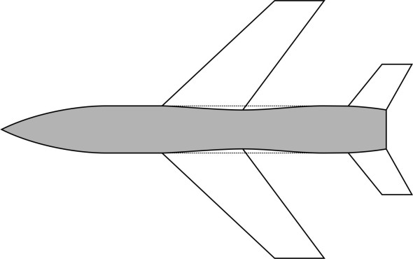
One of the problems with aircraft design is that you can’t accurately determine the aerodynamic characteristics of the wings without taking into account the aerodynamic characteristics of the fuselage, and vice versa. Earlier in Section A1716 we drew attention to the air flow (a) over the wing close to the root, and (b) along the side of fuselage, and how they ‘interfered’ with each other. Such interference is particularly important when the aircraft is flying at supersonic speed. Back in 1951, NASA scientist Richard Whitcomb reasoned that shock waves occur over different parts of the wing and fuselage, extending outwards into the wider flow field where they interact in ways that ultimately determine the total wave drag acting on the body surface. In broad terms, the wave drag is smallest when the cross-sectional area of the wings and fuselage, measured at right-angles to the direction of motion at successive stations along the aircraft’s central axis, varies smoothly from station to station. There are certain places where the cross-sectional area changes abruptly, for example, where the wings jut out sideways from the fuselage – here, it increases sharply, and falls again at the trailing edge. Whitcomb established a principle called the ‘Area Rule’, which stated that any given aircraft will have the same wave drag as a body of revolution whose cross-sectional area at every station is the same as that of the aircraft. Hence if we shape the aircraft so that its total cross-sectional area follows the Sears-Haack profile, its wave drag will be minimised. Among other things, this means reducing the fuselage diameter in the neighbourhood of the wing root as shown in figure 15. When applied in practice, it reduces the drag peak in the transonic regime by a considerable margin, and during the 1950s, this enabled fighter aircraft with limited engine power to break through the Mach 1.0 threshold and achieve a significantly higher maximum speed. In practice the rule was useful for speeds in the range \(0.95{\rm \; }<{\rm \; Ma\; }<{\rm \; }1.3\). For higher speeds, the ‘Rule’ is more complicated [11].
Figure 15
The blended wing-fuselage
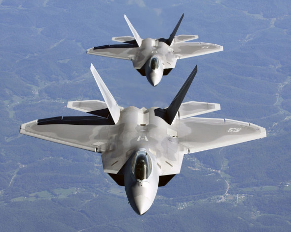
Now we turn to aircraft whose wings blend into the fuselage, so the distinction between the lifting surfaces and the load-carrying compartment is blurred. Typical of vehicles in category are combat aircraft: long-range bombers, and jet fighters such as the Lockheed F-22 as pictured in figure 16. You can see that in some places, it is not clear whether the skin of the F-22 is part of the wing or part of the fuselage. Part of the reason for its unusual shape is the need to disguise the presence of the vehicle from enemy radar. The concept was exploited in other ‘stealth’ aircraft that are beyond our scope here.
Figure 16
With aircraft of this form, analysing the air flow and predicting the aerodynamic forces is more difficult. In the past, designers dealt with conventional aircraft by examining the wings and fuselage separately. This provided useful guidance for decision-making during the preliminary stages of a project: as relatively simple shapes, their aerodynamic behaviour could be predicted using Euler’s potential theory, the Joukowsky theorem, and perturbation methods. No such equivalent exists for a blended wing. However, computer simulation now plays a growing part, revealing aspects of aerodynamic behaviour that can’t be accessed in any other way. Setting up the model grid is expensive and time-consuming, but it is conceivable that in future, artificial intelligence will speed up the process and reduce the overall cost.
Recent developments
Since the early days of flight, designers and manufacturers have aimed to make aircraft fly faster and more safely. We’ll finish this Section with a brief review of developments at the high end of the speed range that have attracted public attention, and might or might not might not happen during the foreseeable future.
Space re-entry vehicles
Typically, the vehicles that move fastest through the earth’s atmosphere are space craft. Some of them carry people. At the end of a mission, the crew must return to earth in a passenger-carrying machine that moves along a controlled flight path. Before making its final descent, the vehicle will go into low earth orbit. Then, it decelerates from its orbital speed – typically 30 000 km/h or more (18 000 miles per hour) to zero in just a few minutes. When a space vehicle re-enters the atmosphere, the aim is not to reduce drag, but to increase it. All the braking is provided by the friction with the air flow, which imposes a heat load on the body surface. It’s striking how the shape of such vehicles has changed since the early days of space flight. During the early NASA space missions, the re-entry stage was carried out in the command module, which was roughly conical in shape. The lives of the occupants depended entirely on the integrity of the heat shield built into the underside of the body surface, which had a blunt profile to slow the capsule down before the vehicle’s parachutes opened for the last stage of the descent (figure 17).
Figure 17
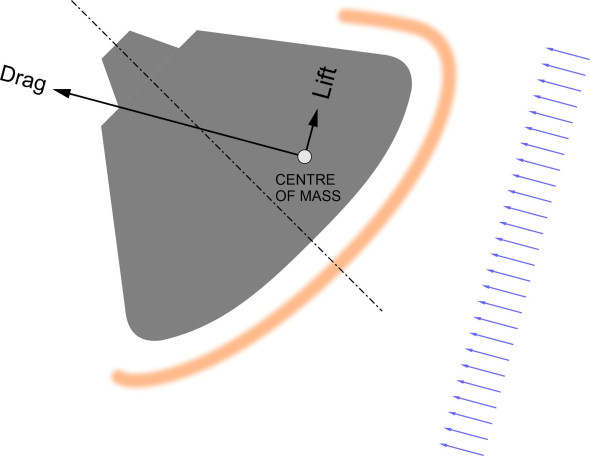
The realisation that a blunt re-entry body was better than a sharp one first came to H J Allen in 1951 at the NACA Aeronautical Laboratory [2]. At time when aerodynamicists were thinking about slender, supersonic profiles, this was a controversial idea. However, it was found that a blunt leading edge worked better because there was the gap between the major source of the heat – the shock wave – and the vehicle body, so much of the heat passed into the air rather than the body surface itself.
Figure 18
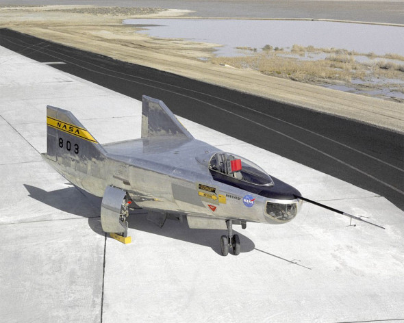
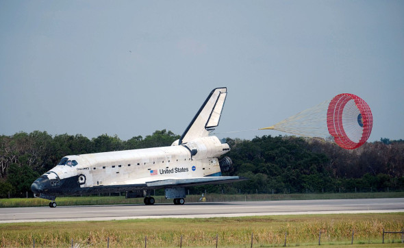
But designers were already working on a reusable system, and experimental re-entry vehicles were developed that could glide through the atmosphere and touch down at an appointed landing place at the end of the mission. Although forerunners of the space shuttle, they had no engine and no wings. A notable example was the Northrop M2-F2, which was essentially a half cone flying with the curved side downwards, that was equipped with two large fins for stability (figure 18). But after a great deal of research and development, the project evolved into what we now call the Space shuttle, a slender delta-winged aircraft whose body was largely covered in ceramic tiles (figure 19). It had a rounded nose and rounded leading edges to the wings, and carried out much of the descent at a high angle of attack, around 40\({^\circ}\) [4].
Figure 19
Aircraft of tomorrow
For many years, it was believed that the future of aviation lay in a new direction: hypersonic flight. Exotic machines would carry passengers half-way round the world in a couple of hours. Among the various proposals was the waverider, essentially a wingless fuselage with a wedge-shaped longitudinal profile. An early form is sketched in figure 20 as seen from the side. It generates a shock wave under the nose that is attached to the leading edge: the increased pressure behind the shock wave provides the lift that keeps it aloft.
Figure 20

The shock wave also compresses the air entering the supersonic ramjet (‘scramjet’) engines mounted roughly amidships, and further aft, the underside of the aircraft is contoured to act as an extension of the engine nozzles. None has yet been built, although some years ago, NASA created a scale model called the NASA X-43. It carried out two flights in 2004, launched from a booster rocket. Other shapes are possible: a summary of the principles involved can be found in Anderson 11 p876-890 [4]. A more sophisticated design that takes into account friction drag, the Boeing X-51, achieved a peak speed of Mach 5.1 during a flight that lasted for 6 minutes. For reasons of cost and environmental impact, it seems doubtful whether this configuration could be developed to transport people and goods over populated areas. Nevertheless, understanding the behaviour of flying machines in the hypersonic speed range may still be important, because the technology can be applied in other fields, for example, defence and space exploration.
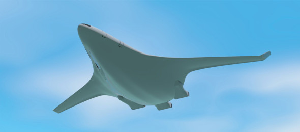
In fact, developments in the world of commercial aviation have focussed on efficiency and the need to minimise environmental disturbance. Design concepts have been proposed for subsonic ‘flying wings’, in which the fuselage is no longer a separate entity. The SAX 40 quiet airliner is one such concept [17]. It was intended to demonstrate that aircraft currently entering service weren’t as quiet or fuel-efficient as they might be (see figure 21). A flying wing could deliver the same service with less fuel and a reduced noise impact at ground level.
Figure 21
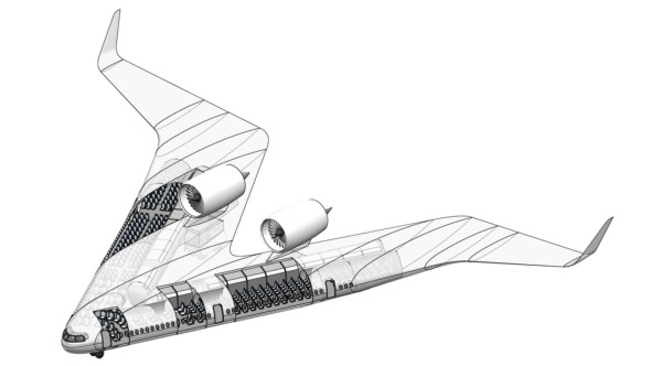
However, an aircraft of this kind is expensive to build. The most practical shape for a passenger compartment is a cylinder, which the designer must somehow integrate into a non-cylindrical skin. And once built, if the design is commercially successful, sooner or later customers will demand an upgraded version with more passenger capacity. It cannot easily be ‘stretched’ to increase the payload: any change in the capacity will mean a complete re-design and re-tooling for production. A more recent example of a blended wing design that appears to overcome this problem is the ‘Flying V’ airliner being investigated by the Technical University of Delft with support from Airbus and the Dutch airline KLM [15]. Essentially, it consists of two cabins joined in a V formation as shown in figure 22. As with the SAX 40, the turbofan engines are located above the wing to reduce their noise impact on the ground. Compared with a conventional aircraft, it is expected to produce a low noise footprint and improved fuel economy.
Figure 22
Finally, it’s worth drawing attention to the experimental QueSST (Quiet SuperSonic Transport) programme. Currently, commercial flight supersonic flight over land is banned in the USA. The aim of the QueSST programme is to determine whether aircraft can be designed to fly at speeds above Mach 1.0 with a relatively unobtrusive sonic boom. The prototype was rolled out in 2024, and will be flown over communities across the United States to collect data about the noise impact on residents, which will provide regulators with the information needed to establish an acceptable noise standard.
Conclusion
In this Section, we’ve glimpsed several generations of flying machine, each faster and more economical to operate than its predecessors. One can imagine them as steps in a continuous process, evolving at a steady rate. But in practice, the more important steps tend to occur in fits and starts. New machines are technically sophisticated and costly to develop, and for radical configurations, the cost has grown beyond the capacity of individual manufacturers. After a promising start, the developers of the Concorde supersonic airliner were forced to rely on financial support from the governments of France and the UK. Ultimately, the project failed, partly owing to public protests about the sonic boom that prevented it from flying over land, and partly because it was expensive to run.
In fact the quest for speed seems to have stalled. The economics of high-speed passenger flight are not helpful: you can fly very quickly between airports, but they are located some distance from the centres of population, so that passengers spend a large part of the journey from door-to-door travelling by much slower modes of transport. Doubling the speed of the aircraft does not halve the total journey time. And priorities are changing. The climate crisis and the need to protect species diversity are, directly or indirectly, weakening the case for high-speed transport. So far, neither seem to have been taken seriously within the air industry, but they won’t go away. Environmental concerns are more important now than they were when the turbojet first appeared, and future revolutions may focus not so much on height or speed, but sustainability. We’ll leave the matter here, and in the following Sections, turn to less controversial issues such as aerodynamic stability and handling.