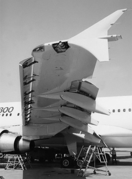
A.1405
Control surfaces
Land vehicles such as trucks and automobiles move around on a more-or-less horizontal surface. Because they grip the road, they can turn to the left or right by swivelling their front wheels, and the driver can be confident the vehicle will move in the direction they are pointing. But the motion of an aircraft is more complicated. It travels in three dimensions, and it cannot easily change direction because it has little grip on its surroundings. Instead, it has adjustable control surfaces, parts of the wings and tail that can change their angle relative to the wind, deflecting the flow of air and causing the machine to pitch, roll, and yaw. To change course, the pilot must use them in combination because there no single steering device of the kind you’d expect to find in an automobile. In this Section, we’ll concentrate not so much on the manoeuvres an aircraft might carry out, but on the movable surfaces that make them happen.
What the control surfaces do
Figure 1
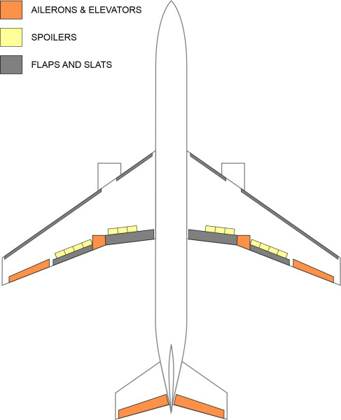
As shown in figure 1, the control surfaces are attached to different parts of the wings, the fin, and the tail. Essentially, they enable the pilot to rotate the aircraft so that it points in a new direction. Each moving surface is attached to the trailing edge of a fixed surface, and normally, the two form a smooth plane. But when the moving surface pivots, together they form a cambered profile, and the result is a transverse force. The greater the angle, the greater the force, and it’s this force that applies a torque to the aircraft that changes its orientation.
Figure 2
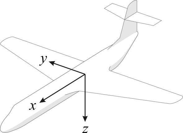
In what follows, we’ll use the frame of reference shown in figure 2. It is tied to the aircraft rather than the surrounding air stream, with the origin located at the centre of mass. Although different from the one we used to explore the air flow in Section A1810, it is the same as the one we adopted for road vehicles and for ships in other parts of this web site. The aircraft can move in each of three perpendicular directions: forwards (\(x\)), sideways (\(y\), positive to starboard), and downwards (\(z\)), but here, we are mainly interested in rotations about the axes. The conventional terms for the three rotations are roll (about the \(x\)-axis), pitch (about the \(y\)-axis), and yaw (about the \(z\)-axis). In each case, the rotation is deemed positive if the direction is clockwise as seen from the origin.
Pitch
We’ll begin with the control surfaces that make the nose of the aircraft pitch up and down – the elevators. They are attached to the ‘horizontal stabiliser’, which on a conventional aircraft is located at the rear (figure 3) and which we’ll call the tailplane. When the elevators hinge downwards, the tailplane effectively becomes a cambered aerofoil and generates lift, so the tail rises and the nose of the aircraft pitches down.
Figure 3
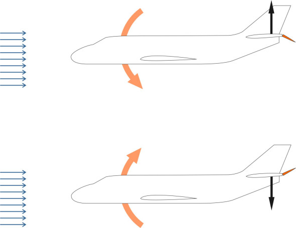
On the other hand, when the elevators hinge upwards, the lift falls and the nose of the aircraft rises. There is also a secondary effect. When the pitch changes, so does the angle of attack of the wings. Imagine the pilot raises the nose by a couple of degrees. As the angle of attack increases, momentarily, the lift rises. However, the drag rises too, and as a result, the velocity falls. It follows that pitch affects airspeed, and as we’ll see later in Section A0415, pilots use pitch as a means of adjusting the aircraft speed without changing the throttle setting.
There is another aspect of pitch control that we have already mentioned in Section A1610. Suppose the aircraft is cruising in steady, horizontal flight, and the pilot raises the pitch to begin a climb. When the elevators rise, they produce a downforce on the tail. The result is that the total lift is momentarily reduced, so the aircraft tends to fall a little before it begins to rise. In most cases the effect is negligible, but as pointed out earlier in Section A1610, with a delta wing it is more severe, and the initial loss of height needs to be considered if the aircraft is flying close to the ground. Another factor with the hinged elevator configuration is that in supersonic flight, the camber is less effective, which is why high-speed aircraft often have a ‘slab tail’, an all-moving tailplane that exerts a more powerful transverse force than a conventional elevator.
Roll
Now we turn to the moving surfaces makes the aircraft roll from side to side. There are two distinct types. The first is the aileron, whose name derives from the French word meaning ‘little wing’. It was first used by the pioneer aviator Henry Farman in 1908 [1]. Typically, the ailerons are attached near the wingtips, where they apply maximum torque around the aircraft’s central axis. In practice, the pilot must restore them to the neutral position as soon as the aircraft reaches the desired angle of roll, otherwise, it will continue to roll indefinitely. In addition, on larger aircraft there is usually a set of smaller ailerons mounted inboard that are used for minor adjustments during straight and level flight, often under the supervision of the automatic pilot.
Figure 4
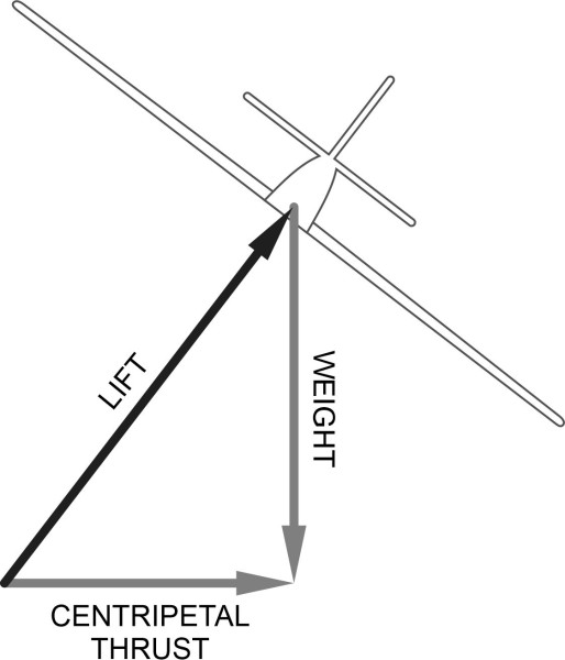
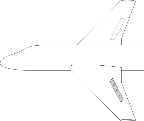
The ailerons play an important part in turning manoeuvres, because in order to change direction, the aircraft must first roll in the direction of the turn. Then as shown in figure 4, the radial component of the lift force provides the centripetal thrust needed to maintain a curved path. While this is the main function of the ailerons, using the ailerons alone can leads to difficulties. When an aircraft rolls to the right, for example, the starboard aileron hinges upwards and the port aileron hinges downwards. The aircraft begins to roll clockwise, but there is an unintended consequence: the port aileron adds both to the lift and drag, which causes the aircraft to yaw in the opposite direction. With smaller aircraft, this can be countered by applying the starboard rudder. But for larger aircraft, another kind of device enters the picture: spoilers. They are small tabs hinged to upper surface of the wing, usually with several on each wing. When a spoiler is raised, it disturbs the air flow and causes it to detach. As a result, the pressure rises and the lift falls. During a turn to the right, it is the spoiler on the starboard wing that rises. It causes the aircraft to roll to the right, and also increases drag on the starboard wing so that the aircraft yaws in the intended direction. During a turn to the left, it is the port spoiler that comes into play, as shown in figure 5. In practice, the spoilers are deployed in conjunction with the ailerons, and to simplify the workload for the pilot, the process is automated.
Figure 5
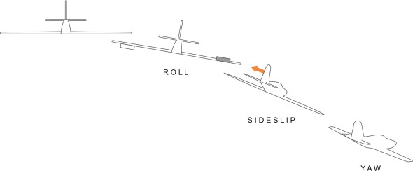
Once the pilot has achieved the required roll angle – to starboard, say – the lift force no longer balances the aircraft’s weight, and it slips sideways to the right as shown in figure 6. The transverse air flow acting on the fin tends to slew the aircraft round, and it yaws to the right as well. It’s sometimes claimed that an aircraft can be flown using only the ailerons for directional control, but as we’ll see later in Section A0415, a turning manoeuvre may need input from the rudder and elevators too.
Figure 6
Yaw
The movable surface attached to the fin is called the rudder. In some ways it is the aeronautical equivalent of a ship’s rudder: we might imagine it turning the aircraft to the right, say, by thrusting the tail sideways in the opposite direction. The rudder is vital during landing and take-off, but once the aircraft is clear of the ground, it only plays a secondary part in directional control, because in practice, turning manoeuvres rely on a combination of control surfaces in which the ailerons play a more important role.
Extra lift
As well as cruising at speed, an aircraft must be capable of taking off and landing, potentially hazardous operations that take place at the beginning and end of every flight. The runway at a commercial airport is typically between 2 and 4 kilometres long. At take-off, the aircraft accelerates as quickly as possible to clear the end of the runway at a safe height: the more lift the wings can produce, the better, but with the least possible drag. When landing, the situation is different. The aim is to approach the runway at a relatively slow speed and at a steep angle, which makes it easier to judge the point of touchdown and allows a greater clearance above any obstruction on the ground. Here, the requirements are (a) lots of lift, and (b) more drag. To protect the wheels and tyres at touch-down, the landing speed of a jet airliner is limited to a value of around 250 km/h, compared with a cruising speed or around 900 km/h. Since the lift generated by an aircraft wing is proportional to the square of the velocity, it appears that for the wings to generate the lift needed to support the aircraft’s weight during the landing approach, the coefficient of lift must somehow increase by a factor of \((900/250)^{2}\), roughly a factor of ten. In principle, one can achieve this partly raising the angle of attack \(\alpha\), but the wings of a jet airliner are relatively thin, and a high angle of attack causes the air flow to separate over the leading edge. The solution is to build high-lift devices into the wings that change the aerofoil cross-section when the aircraft comes in to land.
Slots and slats
Let’s begin at the leading edge of the wing, where slots and slats are located.
Figure 7
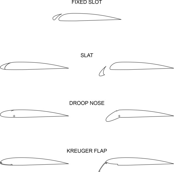
A slot is a permanent gap built into the wing structure as shown in the digram at the top of figure 7. It enables some of the air flowing underneath the leading edge to transfer to the upper surface, and there is no mechanism involved. By comparison, slats are narrow blades attached to the wing that can be extended and retracted so the pilot can open and close the gap as required. The two positions are illustrated in the diagram that appears in the second row of the Figure. It is widely believed that the gap allows air at high pressure to cross from the underside to the upper surface, where it reinvigorates the boundary layer, delays separation, and thereby increases lift. However, this interpretation has been challenged: there are several other factors involved, which are summarised in [3]. A key argument seems to be that every wing generates a vortex that circulates around the aerofoil cross-section, and the gap effectively splits the circulation into two distinct parts: the circulation round the main part of the aerofoil, and the circulation around the subsidiary element at the leading edge. The interaction between the two vortices slows down the air flow over the upper surface of the main aerofoil, which leads to a reduced suction pressure. However, there is less likelihood of separation, and the lift reduction is more than compensated by an increased pressure on the lower surface, resulting in a net increase in lift. During World War II, German aircraft were commonly fitted with a version of the slat that was self-actuating: in normal flight, the air pressure around the stagnation point pushed the slat flush against the leading edge of the wing, but it extended automatically when the angle of attack reached a critical value. Most aircraft designed by the Messerschmitt company were equipped with spring-loaded leading-edge slats, except for theMe 163B Komet rocket fighter, which instead used fixed slots built into the leading edge.
Slats are particularly useful for jet transport aircraft, whose wings are relatively thin and liable to separation over the leading edge at high angles of attack. As well as slots and slats, figure 7 shows two alternative devices widely used in recent years. The droop nose is a straightforward extension of the leading edge that pivots downwards. The Kreuger device is more like a flap that folds out from the leading edge. Both have the effect of increasing the camber of the wing, but the Kreuger device increases the plan area as well.
Flaps
The simplest way to increase the lift on the landing approach is to hinge the rearmost portion of the aerofoil so it can rotate downward at an angle relative to its normal position. This both raises the camber and effectively raises the angle of attack, and the result is increased drag together with an increased the lift coefficient.
Figure 8
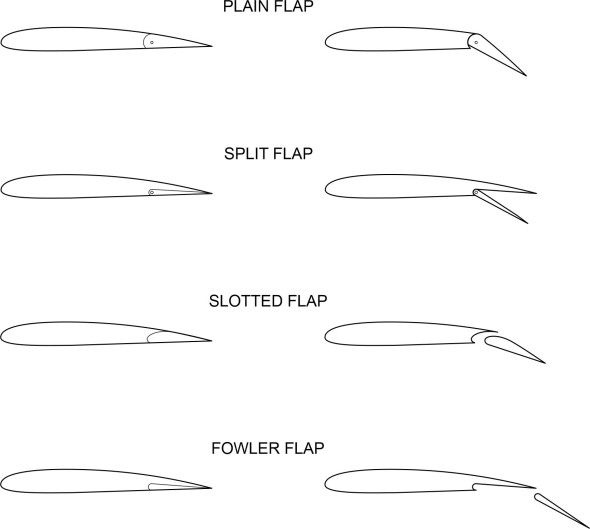
In diagrammatic form, figure 8 shows four kinds of flap that are commonly in use: the plain flap, the split flap, the slotted flap, and the Fowler flap. Slotted flaps are the ones most widely used on large commercial aircraft today. There are also double- and triple-slotted flaps, which aren’t shown in the diagram. The last of the four versions shown in figure 8, the Fowler flap, can raise the lift coefficient by a factor of 2 [2]. It has the advantage that as well as changing the cross-section, it increases the chord and therefore increases area of the wing.
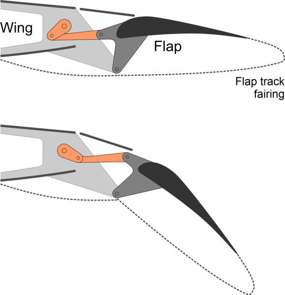
As you might imagine, the mechanism for extending the flaps can be complex. A flap is supported by two or more separate mechanisms, each of which is housed inside a flap track fairing to reduce aerodynamic drag. The apparatus is located under the wing where it does not interfere with the critical low-pressure air stream over the upper surface that provides most of the lift. There are several alternative mechanisms, some of which require intricate mechanical components such as toothed wheels moving along a curved track. The requirements are stringent: the mechanism must work reliably under all loading conditions while adding as little as possible to the weight of the aircraft. The diagram in figure 9 shows the principle behind the system used on the Boeing 787.
Figure 9
Lift spoilers
Slats and flaps provide the extra lift that enables a large aircraft to take off and land at a manageable speed. But not all devices attached to the wing are designed to produce lift. Spoilers do the opposite: they reduce it, while at the same time, increasing the drag. As previously mentioned, they are like small flaps that open out above the wing surface, and can help to steer a large aircraft around a curve during a turning manoeuvre. Here though, we’re concerned with a more basic function which has to do with landing. The idea is simple: once the wheels hit the runway, the pilot cannot apply the brakes straight away because there is insufficient normal force in the contact patch to generate the necessary braking force. For large aircraft, the spoilers help to reduce lift quickly so the wheels can bear the full weight of the aircraft and the brakes can be applied to maximum effect without skidding.
Actuating the control surfaces
Early aircraft were made of wood and canvas. The control column was connected to the moving surfaces by wires that were threaded through the fuselage and wings. If you pulled on the control column, the wires raised the elevators, and the direct connection through the wires gave the pilot a physical sense of the aerodynamic forces acting on the machine. But as speeds increased, the forces increased, and greater effort was needed from the pilot to keep control. Over a long flight, continual buffeting from wind gusts, for example, made flying hard work.
The cockpit controls
Figure 10
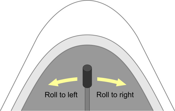
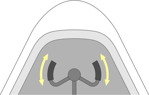
The cockpit controls enable the pilot to rotate the machine around any of the three axes \(x\), \(y\), and \(z\). Movements about the \(x\) and \(y\) axes (roll and pitch respectively) are carried out using the control column. For example, moving the control column to the right causes the aircraft to roll to starboard, while moving it to the left causes it to roll to port (figure 10). However, on larger aircraft the control column doesn’t move from side-to-side. Instead, attached to the top there is a kind of handle-bar. To make the aircraft roll, the pilot will turn it like a steering wheel (figure 11).
Figure 11
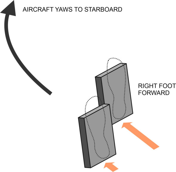
The control column itself only moves backwards and forwards, complete with the handlebar if one is present. The pilot pulls it back to pitch nose-up, and pushes it forward to pitch nose down. Yaw control is carried out separately: the rudder pedal yaws the machine to starboard when the pilot pushes the right pedal forward, and to port when the pilot pushes the left pedal forward (figure 12). Notice that the pedals act in the opposite sense to the steering on a car – a legacy from the early days of flight when the control column was connected directly to the rudder at the tail via steel wires threaded through the fuselage.
Figure 12
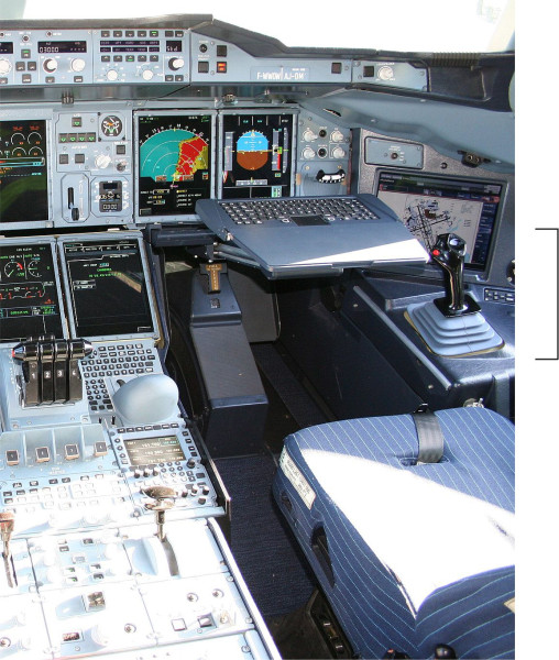
On Airbus jet airliners, the control column is has evolved into a relatively small ‘sidestick’ located to the right of the pilot’s seat. There is no physical connection between the stick and the moving surfaces: the pilot’s control commands are converted into digital signals that are relayed to the relevant parts of the aircraft, and the control column looks more like a computer joystick (figure 13).
Figure 13
Adjusting the balance
During the early days of flight, the control column was connected mechanically to the control surfaces, and the pilot had to apply a significant force, for example, when recovering from a dive. As aircraft grew larger and faster it was necessary to relieve the physical workload, and engineers sought ways to balance the control surfaces so they needed only a small force to move them up and down (or from side to side) against considerable aerodynamic pressure. The same requirement still applies to light aircraft today. The simplest method is to move the pivot point aft.
Figure 14
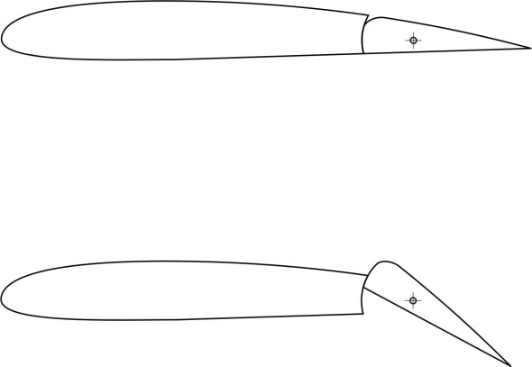
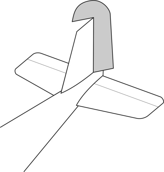
figure 14 shows diagrammatically how this reduces the lever arm and hence the torque that the air flow applies to the control surface [4]. Another method is to extend the control surface – or part of the control surface – ahead of the pivot point. The aerodynamic force acting on the extended ‘horn’ acts in the opposite direction to the force on the main part of the moving surface. On older aircraft, this technique was commonly applied to the rudder as shown in figure 15, and also to the elevators.
Figure 15
These are ingenious methods for easing the pilot’s workload, but they introduce a new problem. In its simplest form, a control surface is like a flat plate, hinged along one edge. If it moves freely, when immersed in a powerful air stream it becomes liable to aerodynamic oscillations, or ‘flutter’. Depending on its weight and the nature of the air flow, the oscillations can grow in magnitude until the control surface becomes damaged or even disintegrates. This has been a peristent problem since the beginning of powered flight, and one of the early solutions was to attach a small weight to the control surface to change its moment of inertia so that its resonant frequency was less likely to be triggered by the air flow.
Actuation mechanisms
As aircraft speeds grew during the first half of the 20th century, designers turned to the possibility of power-assisted controls. An elegant solution was to use the power of the air stream itself to lever the control surface into position, in other words, a ‘servo’ mechanism. As an example of how this works, suppose we want to move an aileron upwards. A small tab built into the trailing edge of the aileron is rotated in the opposite direction, downwards. This creates a local lift force that draws the aileron upward as shown in figure 16.
Figure 16

In effect, this exploits the pressure within the air flow itself to supplement the force applied by the pilot to the control column. At the time, servo tabs made long flights easier, and later, they evolved into trim tabs, which remain standard fixtures on larger aircraft. They are deployed separately by the pilot to adjust for any imbalance in the aerodynamics, and once adjusted, the settings are retained for as long as the aircraft continues at the current altitude and angle of attack.
In the latter half of the last century, as commercial aircraft became more powerful, balanced systems were found to behave erratically as their cruising speed approached Mach 1.0, and mechanical actuation was abandoned. Instead, designers switched to power-assisted control systems more like the power-steering found in road vehicles, with a greater or lesser degree of feedback depending on the mode of application. Such a system has three main elements:
- the actuator or power source that drives the movement of the control surface
- the mechanism that controls the change in geometry as the control surface opens or closes, and
- the link from the cockpit to the actuator, which in principle may be a hydraulic pipe or an electric cable.
Some actuators are driven by electric motors, but most are hydraulic, operated through a cylinder and piston. Such systems require either (a) a central source of pressurised fluid with a local control valve for each actuator, or (b) a local pump system installed separately for each actuator. For larger aircraft, the link to the cockpit is usually through an electrical cable. In principle, the command signal (to raise or lower the elevators, for example) can be analogue or digital, but nowadays the latter is standard, because the link to the cockpit forms part of a wider digital control system.
The control system
So far, we have touched on the mechanical nature of control surfaces and how they influence the aircraft’s motion, but there is another aspect of the problem that we haven’t yet mentioned. Like driving a car or piloting a ship, flying an aircraft is a continuous process. Each moving surface functions as part of a dynamical system that can be represented in terms of a control ‘loop’. A good example is pitch control.
Figure 17
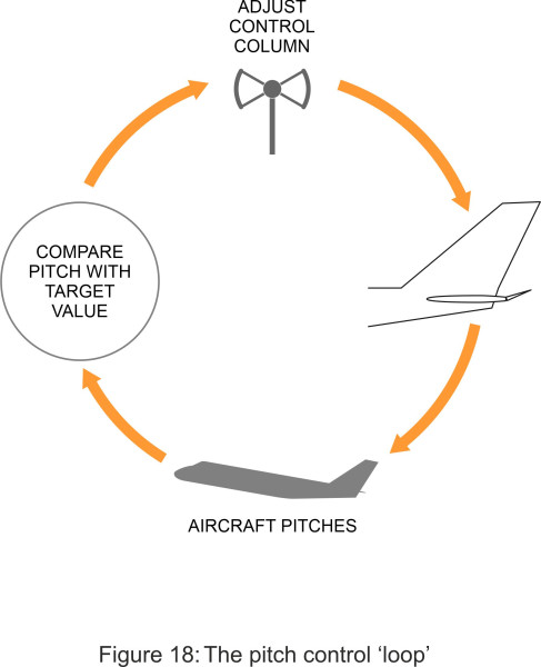
The diagram in figure 17 shows how the process works. It begins with the pilot, who issues a command through the control column that is passed to the elevators. The elevators rise or fall as requested, which causes the aircraft to pitch nose-up or nose-down. But the process doesn’t end there. The pilot sees how the aircraft responds, and if the change in pitch is greater or less than intended, will adjust the position of the control column accordingly. The process of adjustment continues, maybe through several iterations round the control loop, until the pilot is satisfied with the outcome. Mostly, it’s an unconscious process; what is significant is the delay between each command and the aircraft’s response as seen by the pilot. Delays can arise from several different sources. For example, it takes a few milliseconds for an adjustment applied to the control column to trigger the actuators that move the elevators up and down. A large aircraft has considerable inertia, and it may take a while to respond. Finally, there is a time lag while the pilot assesses the outcome and decides what to do next.
In this example, we’ve assumed that the pilot is behaving cautiously and working towards the target via small changes in the position of the control column. However, if the pilot’s initial command overshoots the target and the pitch rises or falls beyond the value intended, the pilot must reverse the trend by moving the control column in the opposite direction. This may result in a series of commands and responses that does not converge on a stable flying condition. Instead, the system oscillates out of control, and the greater the delay between the issuing of each command and the pilot’s assessment of the outcome, the more likely it is that the system becomes unstable.
Unstable behaviour of this kind occurs not only in aircraft flight but all manner of engineering control processes in which the system is programmed to seek a defined target, and which may or may not involve human decision-making as part of the control loop. They have been widely studied, and research has led to mathematical models that predict their behaviour. We won’t go into the maths here, but instead, point out that for a large aircraft, it is usual practice to have the pilot’s input commands supervised by a computer system that moderates them when required to protect the safety of the aircraft. Note that digital communication plays an important part in such a system: ideally, the pilot’s commands are routed through an electrical cable to the central processor before being passed on to the moving control surface itself. Other issues arise in connection with what happens if the power controls fail, and whether the system should create artificial feedback to that gives the pilot a more direct sense – through the control column – of what is happening to the aircraft.
Figure 18
