A.1005
Air frame
A flying machine is more than an aerodynamic projectile. It is also a structure. Although slender and light in weight, it carries loads that are applied to its surface and transmitted from place to place inside. Some are external loads such as the air pressure acting on the wings and tail, together with forces from the undercarriage when it is supporting the machine’s weight on the ground. There are also internal loads, such as the air pressing outwards on the walls of the fuselage when the aircraft is flying at high altitude, and the weight of the fuel, passengers, and cargo. Finally, there is the weight of the structure itself, which in a modern airliner accounts for roughly a third of the total [17] [7]. When designing an aircraft, the engineer pares down each component to its minimum possible size and weight, and at the same time, tries to ensure it will not break or distort so that it functions safely over the whole of its planned life. The two main goals – minimum weight and reliable performance – are directly in opposition, and to achieve a successful balance requires a combination of sophisticated engineering design, high-quality materials, and a tightly disciplined system of maintenance.
Structure
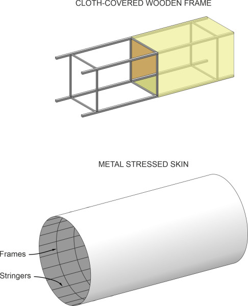
Early aircraft were very different from the airliners we travel in today. The core structure was an open framework of wooden spars and struts. It was braced with wire to keep it rigid, and covered with canvas or silk to form a more-or-less smooth aerodynamic surface. Although flimsy, an open framework kept the weight down so the aircraft could fly given the limited power available from the engines and propellers available at the time. However, the situation changed as the engines became more powerful and the framework was exposed to greater aerodynamic forces. The fabric covering was replaced by metal sheet, and because a metal sheet could handle significant loads, the inner frame became less important. Around 1920, the Northern Irish company Shorts produced one of the world’s first aircraft with an all-metal monocoque fuselage, made from the aluminium alloy ‘duralumin’ [1]. As shown diagrammatically in figure 1, for a monocoque fuselage the skin became the main structural member, while the frames and stringers defined the body shape and stiffened the skin so it didn’t buckle under compression.
Figure 1
Wings and tail
In flight, the main load acting on an aircraft wing is the lift force. It bends the wing upwards, creating stresses in the wing cross-section. The stresses vary from point point to point along the span, being small near the wingtip and rising to a maximum at the root. Essentially, the wing surface is a flat box, not an ideal shape for carrying a load of this kind. So much of the load is carried by an internal spar or multiple spars that extend from the root to the wingtip. For lightness the spars are narrow boxes with reinforced roots that are bolted to the fuselage. In some cases, the spar takes the form of a continuous beam from wingtip to wingtip, with the fuselage bolted on top. The remaining load is carried by the stressed outer skin, which is stiffened by stringers running parallel to the leading edge, together with ribs whose curved outline defines the aerofoil cross-section (figure 2).
Figure 2
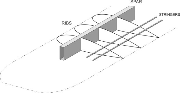
Figure 3
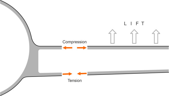
At each point along the span, the upper surface of the wing spends most of its flying hours in compression and the lower surface in tension as shown in figure 3. Also, the lift can make the wing twist. As we’ll see later, this changes the angle of attack and disturbs the wing’s aerodynamic behaviour. Hence torsional stiffness is vital. Twisting loads are handled by the wing spars together with the outer skin, both of which are designed to resist torsional deformation. Since the stresses vary across the wingspan, the skin thickness varies too. For a large aircraft, it can be 25 mm thick at the root, tapering off to a minimum at the tip. In the USA, the smallest permitted thickness is 1.4 mm. This is intended to protect the material from lightning strikes [15], which can melt a thin metal sheet. For large aircraft, the wing is assembled from separate panels. Some are made from sheet metal, while in other cases, the skin of each panel together with the ribs and stiffeners is machined from a solid slab to reduce the number of connections, which are potentially weak points in the structure.
The tail of an aircraft consists of two fixed surfaces, the fin and tailplane. They do not contribute to lift, and unlike the wings, don’t carry heavy loads. But they must be large enough to stabilise the aircraft when it is flying at a high angle of attack and the tail is blanketed by the turbulent wake from the fuselage. This is why the fin on a large jet airliner today is so tall. The fin and tailplane also support the moving surfaces (rudder and elevators) that control the aircraft’s direction of motion, and as we’ll see shortly, the mountings must be sufficiently robust to prevent oscillations. Hence the designer aims for a stiff but lightweight structure. It is here that composite materials and sandwich sheet have a major role, and production is often outsourced to a specialist contractor.
Fuselage
Almost all transport aircraft have a cylindrical fuselage. For aerodynamic efficiency, it is rounded at the nose and tapered at the rear, but for most of its length the fuselage is circular or nearly circular in cross-section, as defined by transverse frames at regular intervals from front to rear. When stiffened by longerons or stringers, the skin has considerable resistance to buckling under compression so it can carry a high bending load. It also has the advantage that it can be assembled from short sections built to a more-or-less standard pattern. Moreover, an existing design can be upgraded to carry a greater payload by adding a new section, without necessarily having to re-configure the rest of the air frame. You’ll recall from Section M1508 that a similar process occurs in the shipping industry too. It’s much easier to ‘stretch’ an existing design than to create a new one.
The fuselage carries two main loads. The first is the pressure of the air inside. Jet aircraft fly most economically at altitudes in the region of 10000 m where the external air pressure is a small fraction of the atmospheric pressure at ground level. To enable the passengers and crew to breathe normally, the fuselage is pressurised so there is a net pressure difference acting outwards on the fuselage skin. This creates tensile stresses both in the longitudinal and circumferential direction, which tend to stretch the fuselage like the skin of a balloon. Added to the effect of pressurisation is the weight of the fuselage itself together with the weight of crew, passengers, and cargo. Since the fuselage is cantilevered forward and aft of the wings, these loads create bending moments that in turn add to the tensile stresses acting lengthwise along the upper part of the fuselage cylinder together with a component of compressive stress in the lower part. Notice that when the aircraft is flying at a low altitude, the effect of pressurisation diminishes and the compressive stress component increases - the loading pattern in the air is different from the loading pattern on the ground. For commercial aircraft with a pressurised fuselage, parts of the fuselage skin undergo a complete stress cycle from negative to positive on every flight.
When designing the fuselage, the engineer must reckon with other complications too. For example, there are ‘discontinuities’ in the structure where the outer skin or the load-carrying members change shape. The key locations are around the cockpit canopy, the passenger doors and windows, the undercarriage doors, and other ‘cut-outs’ that allow maintenance access to internal equipment [12]. As we’ll see shortly, unless these areas are strengthened, they create stress concentrations that can shorten the vehicle’s life.
Materials
Aircraft are built largely from metal sheets and stiffeners, together with a growing proportion of composites, for example, plastic panels reinforced with glass fibre. Metals are stronger than most other materials, and although they flex a little under load, they return to their original shape after the load is removed. Steel is one of the strongest, but it is rarely used in aircraft construction because of its high density and the speed at which it corrodes in the natural environment; it can be found mainly in the undercarriage, the wing root attachment, engine supports and flap tracks [17]. By contrast, aluminium alloys, which first became available during the 1940s, are light in weight, can carry a relatively large load, and are more resistant to cracking as well as less liable to corrode. Each wing is a highly-stressed box, and different grades of aluminium alloy are used for the upper and lower surfaces: in flight, the lower surface undergoes tensile stresses and must resist being pulled apart, while the upper surface needs to be stiffened to resist buckling. Titanium is even better. Although expensive, it can withstand corrosion and copes with operating temperatures up to 150\({^\circ}\)C. Hence it is particularly useful for high-speed aircraft, and in the form of various alloys, it accounts for 10% of the structural weight of some airliners [17].
As a useful alternative to aluminium, composite sheets can be used for panelling large areas of the aircraft surface to create a light and resilient skin. The first composites were made from carbon fibre embedded in epoxy resin, a plastic that on its own, is relatively weak in tension, but when the fibres are suitably aligned, forms a rigid and serviceable plate. Carbon fibre composites were developed in the early 1960s. Glass-reinforced plastics (GRP) have been used in the construction of sports cars and small boats for some years, and are now appearing in the aircraft industry as well. Originally, they found their way into small aircraft construction because they were light and easy to handle. For example, Bert Rutan used plastic foam bound with a GRP skin as a material for his tiny ‘Vari-eze’ machine. But now they are appearing in large aircraft. The giant Airbus A380 contains panels made from GLARE, an innovative structural material consisting of an aluminium laminate containing sheets of glass-fibre reinforcement that act as a crack-stopper [14]. The airframe of the Boeing 787 Dreamliner is 50% composite and only 20% aluminium alloy [4].
Sandwich sheet
Figure 4

Until now, we have dealt with sheet materials made from aluminium alloys and reinforced plastics. They are thin, which means that however strong the material in its raw form, they are not very efficient. Imagine you are bending a plastic ruler over your knee, pressing down on both ends. Because it resists stress, the ruler gives way a little and bends. The highest stresses occur at the outer surfaces: the upper surface stretches in tension while the lower surface is compressed (figure 4). Within the core material, the stress varies between these two extremes, passing through zero in between. The diagram shows that most of the bending resistance comes from the material close to the surfaces, while the material in between is important but in a different way. Without it, the upper and lower surfaces would simply slide over each other, but instead, the core supplies a shear force that ensures the different parts of the cross-section work together as a whole. To achieve this, it does not need to be as strong – or as heavy – as the material at the top and bottom. Depending on the circumstances, balsa wood, cork or plastic foam may be sufficient. It follows that the designer can save weight by using a sandwich structure that will be almost as rigid as a solid material, but significantly lighter. Such materials have been used in aircraft construction for many decades, and the Boeing 747 of 1969 was originally designed with a high proportion of sandwich sheeting incorporated into the structure, mostly in parts that are not expected to carry heavy loads, such as the flaps, the belly fairing, and parts of the tail [5]. Sandwich sheet was used extensively for early Airbus models too.
Figure 5
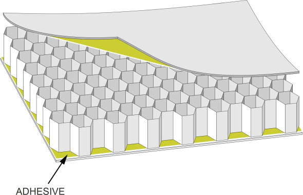
Within the aircraft industry, the most widely used sandwich material is built up from upper and lower facing sheets together with a honeycomb core as shown in figure 5. The cells in the honeycomb are hexagonal in cross-section and only a few millimetres in diameter, made typically from aluminium or Nomex strips folded and glued to the faces with epoxy-based resin adhesives. The material that makes up a Nomex honeycombcore is aramid paper, impregnated with phenolic resin, and the resulting sheet is surprisingly rigid and light in weight. When assembled into the aircraft structure, the edges of each panel are filled with resin to stiffen the panel as a whole. However, the future of sandwich materials for larger commercial aircraft seems to be in decline. In more recent models such as Boeing 787 and Airbus A350 and A380, it has given way to stiffened composites [5]. This may be due partly to safety regulations. As a condition of issuing a certificate of airworthiness, the licensing authorities require new aircraft that contain honeycomb material to undergo a time-consuming and expensive regime of safety tests. Nevertheless, for light aircraft, the use of sandwich materials is growing.
Loading and distortion
In our homes, we are surrounded by objects that keep their shape because they’re made from rigid materials: pots and pans, for example. But if we examine them more closely, we find they’re not so ‘rigid’ as we imagined. If we put them under stress, their shape will change. When lightly loaded, the change is too small to see, but when the load increases beyond a certain level, something else happens. You can bend a teaspoon out of shape, and when you let go, it remains out of shape. Some, like a tea-plate, will snap and break into pieces. Engineers design vehicles so their components are not over-stressed: the loads remain within acceptable limits so that when in service, the object doesn’t deform sufficiently to prevent it carrying out its role, and after the load is removed, it regains its original shape. For materials of a certain kind, the deformation is proportional to the load, so that doubling the load produces twice the deflection. A material that behaves in this way is called ‘elastic’ – in fact, the whole vehicle may be ‘elastic’ in this sense. In Section M1015, we saw how a ship’s hull is sufficiently flexible to sag between waves. Aircraft will flex too, and it has been said that the cabin of a large airliner is divided into separate compartments so that the passengers don’t notice.
Static loading
So we visualise a vehicle as responding more-or-less elastically to loads that arise while it’s in motion. At this point, we should clarify what we mean by ‘loads’. A load is a force applied to the structure usually in one of three ways. The first is the weight of the passengers and goods on board, which doesn’t vary much during the journey, together with the fuel load, which does vary but steadily and at a predictable rate. The second is the weight of the structure itself. The third consists of external loads. For an aircraft in flight, the external loads are the aerodynamic forces applied mainly to the wings and tail that keep the aircraft flying straight and level. Of course, when it lands, like any earthbound vehicle its weight is supported by reactions supplied through the contact patch on each wheel, and these reactions are routed into the vehicle structure in a different way. Here, however, we’ll stick to the aircraft in flight. The aerodynamic load components that remain steady throughout the journey we refer to as ‘static’ loads. They are easy to quantify. We include in this category the lift and drag together with the thrust of the engines; they don’t vary much when the aircraft is cruising at a steady speed and height. Aircraft today carry much greater loads than used to be the case. Since the arrival of the DC-3 airliner in 1935, static loadings on aircraft wings have tripled [17].
Dynamic loading
Dynamic loads occur whenever the pilot makes a manoeuvre, and they also vary from moment to moment depending on what is happening in the surrounding atmosphere. The air is never entirely still, and in unsettled weather conditions, wind gusts can disturb the pattern of air flow and apply significant forces to the aircraft wings and tail. The highest gust loads occur near the ground, and there are ‘design gusts’ that aviation authorities require an aircraft frame to resist. The simplest form is a vertical column of air in downward motion that the aircraft meets suddenly in horizontal flight. To give you some idea, the design gust for a commercial aircraft travelling at cruising speed was once fixed at 50 feet per second, which is roughly equivalent to 34 mph or 55 km/h. More recently, the standards have broadened to include design gusts that rise from zero to their maximum velocity over a finite distance; further details can be found in [10]. This is a single, extreme event that few aircraft are likely to encounter in their lifetime. Other wind forces take on a different form. For example, turbulence can exert a force that varies randomly over time, which may set up a resonant bending vibration in the fuselage, for example.
Figure 6
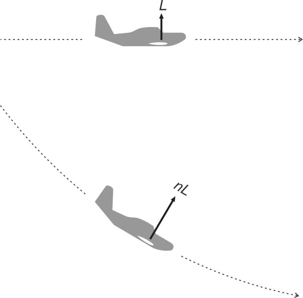
The second main category consists of loads that arise during aerial manoeuvres. Assuming it maintains a constant speed, when an aircraft turns, the forces on the wings increase. The same happens when it pulls out of a dive: to return to level flight, the pilot hauls back the control column and the nose pitches up. The result is a curved trajectory as shown in figure 6. To maintain a curved trajectory, there must be a centripetal force acting at right-angles to the direction of motion, towards the centre of curvature – in other words, the wings must produce more lift. The varying load that acts on the wings during an aerial manoeuvre is conveniently expressed in terms of a load factor. It is the ratio \(n\) of the current load to the load imposed when the aircraft is flying straight and level, when the load on the wings equals the aircraft’s weight. So:
(1)
\[\begin{equation} n\; =\; \frac{L}{W} \end{equation}\]Since there is a limit to the load any wing can carry, there is an upper limit to the ratio \(n\). It’s called the limiting load factor. The limiting load factor varies with aircraft speed and altitude, and it is common practice to present the different values in the form of a ‘\(V\)-\(n\) diagram’ [9]. The air regulation authorities set limiting values on the load factors for commercial aircraft that are typically in the region of 3 to 4 in the upward direction and 1.5 in the downward direction [2], while those for military aircraft and for machines designed to carry out aerobatics are greater.
Aerolastic phenomena
The forces just described assume that the shape of the aircraft is fixed. But in reality, like any structure it deforms a little under load, and the change in shape itself may alter the applied force. For example, the wings will bend up and down, and they may also twist. The changes are small but they have a significant effect on the vehicle’s aerodynamic behaviour. Picture an aircraft with straight wings flying straight and level at constant speed, and focus on the port wing. In figure 7, we see it viewed from the wingtip looking towards the fuselage.
Figure 7

Whether or not it will twist depends on the distribution of air pressure over its surface, relative to an imaginary line drawn through the wing cross-section from root to tip. It is called the flexural axis. To keep things simple, we’ll assume it is a straight line at right-angles to the aircraft’s direction of motion. As shown in the central diagram, if the resultant lift force passes through the flexural axis, the wing bends upward while the torsional deflection is zero. But if the lift passes on either side, the wing will twist. In the upper diagram of figure 7, we see the lift force applied a little way behind the axis. It tends to twist the wing nose-down, in other words, the angle of attack decreases and the lift falls. This is a stable situation. In the lower diagram, we see the lift force applied ahead of the axis. Here, the torsional deflection is in the opposite direction: the angle of attack increases and the lift rises, which makes the torsion worse. This phenomenon is called divergence. It is self-reinforcing, so the distortion increases, and if the wing lacks adequate torsional stiffness, it may fail. In some respects therefore, the ability of the wing to resist twisting forces is as important as its ability to resist bending.
Figure 8
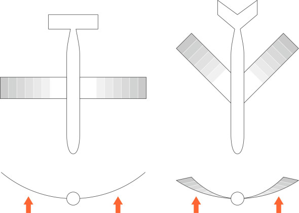
The problem is less acute with swept wings because the flexural axis does not lie along the chord centre. As shown in figure 8, the lift force in the outboard section of the wing tends to twist the whole wing in such a way as to reduce the angle of attack, so the system is stable. Only if the wings are swept forward does the twist increase the angle of attack and lead to divergence.
But as well as divergence, torsional deflection can affect the wing’s response to aileron movements. When the pilot moves the control column to the right, for example, the port aileron hinges downward while on the starboard side, the aileron hinges upwards. The intention is that the lift on the port wing should increase while the lift on the starboard side decreases, causing the aircraft to roll to starboard. However, if the wings are flexible in torsion, the movements in the ailerons may have an unintended effect: the airflow passing over the port aileron exerts an upward force towards the trailing edge of the wing that tends to twist it around its torsional axis, so the angle of attack decreases and the lift falls. We now have two opposing effects: the aileron raises the lift while the distortion of the wing as a whole reduces it. The same phenomenon occurs on the starboard wing: the distortion of the wing opposes the effect of the aileron movement. Under certain circumstances, the result is the opposite of what the pilot intends: the control system is effectively reversed and the aircraft rolls to port. In the past, several aircraft were affected in this way, one of them being the Boeing B-47 bomber of 1951, which had long, flexible wings [17]. Since that time, designers have resolved the issue by moving the ailerons inboard where they have less influence on the torsional deflection, and the rolling action is assisted by spoilers mounted on top of the wing.
Flutter
In addition to divergence and control reversal, there is a third issue that arises from the flexibility of an aircraft wing: ‘flutter’. It has dogged aircraft design since the early days of flight, and remains an important topic on the aeronautical research agenda [6]. It is called flutter because it involves oscillations that aerodynamically, have much in common with the way a flag moves in a breeze. Flutter can affect different parts of an aircraft, including the fin, rudder, tailplane, elevator, engine nacelles, and fuselage panels. We can only give a brief summary here, and we’ll concentrate on the most serious category, wing flutter. It has two components: a torsional oscillation and an up-an-down oscillation. The two are mechanically coupled, meaning that they act together in a synchronised fashion.
To understand what happens, let’s begin with the three kinds of force acting on the wing:
- lift,
- inertial forces associated with the mass of the wing, and
- the elastic forces.
The lift force comes from the surrounding air flow, and it varies with the angle of attack. The inertial forces arise from the wing’s mass: it resists being accelerated up or down, but once in motion, it will keep going and owing to its momentum, will apply a force to anything that gets in its way. The elastic forces have to do with the stiffness of the material – it resists deformation and will react against any object that pushes it away from its equilibrium position. Three forces come into play when the wing moves away from its reference position in straight and level flight, and each has multiple effects. Take the aerodynamic lift, for example. We have already seen from our discussion of divergence that the lift not only makes the wing rise or fall, but it can also twist the cross-section at the same time. The same applies to the inertial and elastic forces. To understand the outcome, we’ll trace the motion of a wing as it rises and falls during a single cycle.
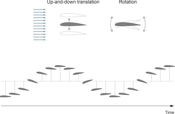
Suppose there is a brief gust of wind that increases the lift. For most wings, the centre of lift lies ahead of the flexural axis, so as is the case with divergence, the angle of attack increases as the wing bends upwards. This leads to a further increase in lift that causes the upward movement of the wing to accelerate while the angle of attack continues to increase. Normally, the elastic forces would resist the deformation and the rise would halt at some intermediate level. But the wing masses have acquired inertia that carries the upward deflection beyond this point. Notice, however, that the centre of mass usually lies behind the flexural centre so that on the upward stroke, the inertial forces tend to twist the wing in the opposite direction, reducing the angle of attack. So the aerodynamic forces abate while the elastic forces bring the upward motion to a halt. At this point, there is potential energy stored in the wing components, which tend to spring back to their initial position, so the wing begins its downward stroke, now at a negative angle of attack. Assisted by negative lift, it acquires momentum in the downward direction, and passes through the reference position to execute the next part of the cycle. Roughly speaking, it is a mirror image of the part we have just described. Throughout, the inertial forces are roughly 90\({^\circ}\) out of phase with one another as shown in figure 9, and depending on the aircraft speed and the stiffness of the structure, the cycles may continue and possibly grow in magnitude over time.
Figure 9
Flutter in an aircraft wing tends to arise at a particular speed called the critical speed. When the aircraft is travelling below the critical speed, any disturbance such as a wind gust may cause a deflection, but the resulting oscillations quickly die away. When it reaches the critical speed, the oscillations persist at a stable amplitude. At speeds above the critical speed however, the oscillations grow indefinitely until the structure is damaged or destroyed.
Over the decades, many aircraft have been lost in this way. So, can flutter be prevented, and if so how? In practice, the designer raises the critical speed to a value well above the speed that the aircraft can achieve in normal service. We’ve already hinted that the key factors are firstly the stiffness of the wing, and secondly the locations of the aerodynamic forces together with the wing’s centre of mass relative to the flexural axis. One obvious remedy is to stiffen the wing structure as a whole. This will usually involve extra weight. Another approach is to re-locate the existing masses so the centre of mass lies ahead of the flexural axis, for example, by concentrating the spars towards the leading edge, or in the case of aircraft with wing-mounted engine nacelles, mounting the nacelles well forward of the leading edge [13].
Failure
Every day, we put our trust in vehicles that carry us around. Occasionally, they break down because certain parts wear out or don’t work properly. This is a particular concern for airline operators, since a failure of almost any kind in a passenger aircraft puts peoples’ lives at risk. This is why engineers worry about every detail of the design, and air regulation authorities keep close track of what is happening within the industry. Among other things, it is vital to know what types of failure commonly lead to accidents. Surprisingly perhaps, we don’t know. Only two or three decades ago, there was an identifiable pattern in the failure of certain components [16]. Failure of the undercarriage during take-off or landing came top of the list, followed by engine breakdowns, then structural defects in the fuselage and wings. Nowadays, the more prominent issues have been ironed out, so that commercial air travel is safer, with casualty rates per passenger-trip much lower than other modes of transport. There are no longer enough crashes that by themselves, reveal a clear pattern or point to ways in which improved aircraft design might reduce their frequency [8]. Most accidents are caused by a combination of factors including human error, though not necessarily pilot error. Ageing of the aircraft structure and systems, maintenance failures, and weather can all play a part in a single crash. The designer’s task is to imagine the possibilities and ensure that, as far as possible, the specification for a new model prevents them from happening within the design life of the machine.
The hostile environment
One of the advantages of flying at 10 000 m is that there is little turbulence to disturb passengers or cargo. But it is still a hostile environment for a lightweight metallic structure. The air temperature is around -50\({^\circ}\) Celsius, and some parts are subject to corrosion from condensation. There is also leakage from galley and toilets, and electrogalvanic reactions between components made from different metals. Just as important is the load acting on the wings as they develop the lift needed to carry the machine off the ground, and the change in air pressure acting on the fuselage that occurs at high altitude. Each component of the aircraft structure is put under stress that varies over a wide range during every flight. In a railway truck or a lorry chassis, such events might not matter: you can replace the weaker members by thicker ones so there’s plenty of material to carry the load even after years of use. But as noted earlier in Section A1716, each kilogramme of weight added to an aircraft structure requires more lift from the wings, which in turn implies more drag, extra fuel, and a reduced payload. And many parts of the aircraft are buried inside a complex structure such as a wing spar that cannot readily be inspected for faults. This raises a problem that has grown in magnitude with every generation of flying machines since the appearance of the first all-metal aeroplane in the early 20th century: fatigue.
Fatigue
The strength of a steel or aluminium component does not remain constant throughout its service life. Earlier in Section M1015 we encountered a notorious example: the effects of metal fatigue effects in ships, specifically the ‘Liberty ships’ that brought supplies to western Europe during the 1939-45 war. Metal fatigue is defined as the progressive deterioration of strength leading to failure at a lower stress than the recognised ‘ultimate stress’ for new material, where the ultimate stress is the maximum that arises at or before the point of fracture. There are several types of fatigue failure, but the one that concerns us here is cyclic fatigue. It arises from cracks, not as a result of high stress as such, but cycles of stress change in which the load rises and falls over time. As explained in Section M1015, stress tends to concentrate around the tip of any indentation in a structural member, and under repeated changes of stress, a tiny crack will grow. This makes the stress concentration worse, so that after a number of cycles, the material fails completely. The problem of metal fatigue came to public attention during the 1950s with the disappearance in flight of two de Havilland Comet jet airliners, losses that were later shown to have been caused by metal fatigue. The phenomenon was not as well understood then as it is today, and the Comet suffered from being the first of its kind to operate such an intensive operating schedule involving pressurisation and de-pressurisation of the fuselage. Detailed aspects of the production models such as rivet holes and a square access hatch were implicated in the failure, and later versions were re-designed with improved production methods and a thicker skin.
We now know that aircraft fatigue levels are high during taxying, take-off, and landing, also under the action of wind gusts, especially close to the ground. Hence, the fatigue life depends not on the number of flying hours but on the number of flights [11]. There are things the designer can do to mitigate the problem. First, there is the choice of material. Metal alloys are constantly being developed that are lighter in weight or have greater fatigue resistance, or some combination of the two. Second, it helps to avoid re-entrant angles and abrupt changes in thickness of any structural member, because these are places that attract high stress concentrations where cracks are likely to start. In aircraft wing and fuselage panels, the material should be thicker around bolt holes, and the holes themselves can be reamed to smooth the internal finish and eliminate small irregularities.
Design criteria
It is an exacting task to design the different parts of an aircraft. Each part should be strong enough to perform its function – but not so strong that it carries superfluous weight, or costs more than necessary. There are two main steps in the design process. The first is to establish the ‘limit load’, the maximum load that the component is expected to encounter during its design life, and the second is to specify the shape, size, and material from which the component is made so that it can sustain the limit load without losing its shape. Inevitably, the limit load is an estimate and the engineer must allow for uncertainty. This is done by adjusting the limit load upwards. The adjusted load is known as the ‘ultimate load’, usually taken as 1.5 times the limit load. You can think of it as a factor of safety to cover unforeseen circumstances. This is what civil engineers do when designing a bridge, for example, or a skyscraper. Surprisingly, the safety factors used in aircraft design are lower than those used in building construction, perhaps because (a) any extra weight in an aircraft carries a large penalty, (b) aircraft are examined repeatedly during their lifetime, and (c) compared to a skyscraper, their lives are relatively short.
With aircraft, it turns out that fatigue is the dominant ageing mechanism. Towards the end of each flight, when an aircraft lands the wings droop downward so that the stresses in the upper and lower skin are reversed. Also, the effects of pressurisation vanish, which changes the stresses in the fuselage. Each flight creates a major upheaval in the structural loading pattern. Designing for a single value of the maximum load is no longer appropriate, and the target is better expressed in statistical terms: for example, the probability of a disastrous fatigue failure during its operational life should be less than \(10^{-7}\) under the action of the repeated and varying loads expected in service [11]. The question becomes how long will the aircraft last? For many years, the guiding principle was that of a safe life for each component. This was the period over which, based on known rates of crack propagation, the component was expected to operate with no catastrophic damage. The method relied on a safety factor to cover uncertainty, for example, by assuming a safe life equal to one fifth of the theoretical value [17], at the end of which the component had to be replaced whether or not there was any sign of fatigue. This approach led to components that some thought to be heavier than necessary. Moreover, the estimates of the safe life were not very reliable because there was considerable scatter in the statistical data, and in any case, the likelihood of fatigue failure was strongly influenced by the way an aircraft was operated and maintained, which was outside the designer’s control.
Conclusion
Designers now combine the notion of a safe life with the fail-safe concept. As a matter of principle, the aircraft is designed so that if a component fails, the load is absorbed by other components until the damage is detected and repaired. In effect, the process of inspection and repair is part of the design, taking place at a frequency sufficient to ensure that the crack cannot grow to catastrophic size before being noticed. The result is an operational regime that tolerates damage [17], with aircraft safety depending on regular inspections using ultrasound or other specialised equipment in places that are not necessarily easy to access. Airbus vehicles are required to have a ‘fatigue life’ of 24 000 flights without fatigue cracks, and double that number with the approved programme of inspection and repair. Uniquely across the transport field, the safety of vehicles has become a matter not just of engineering precision in design and manufacture, but control of the way vehicles are inspected and operated on a daily basis throughout their working lives.