A.0418
Stability
Throughout this web site we’ve followed a common thread. It has to do with the way vehicles move, how their weight is transmitted to their surroundings, and how we can prevent them from rolling over or lurching away from their intended path. Land vehicles and water vehicles are easier to deal with, in the sense that they travel in a roughly horizontal plane, so we are mainly concerned with their directional control, and specifically, how they yaw from side to side. But aircraft move in three-dimensional space. Not only can they yaw from side to side, but they can also roll to the left or right, and pitch up and down. In many cases, two or three of these motions interact, making it harder to track what is going on. Triggered by wind gusts for example, the interactions offer a pathway for the transfer of energy from one kind of motion to another and back again: the stage is set for a variety of oscillations that the pilot (or the automatic pilot if there is one) tries to anticipate and damp down before they get out of hand. In this Section, we’ll be looking at the different modes of instability, and how an aircraft can be designed to cope with them.
Aircraft motion
By way of preparation, we’ll run through some aspects of aircraft motion that are relevant to the problem together with the frame of reference against which the movements are defined, and try to define ‘stability’ in practical terms.
Relevant motions
Figure 1
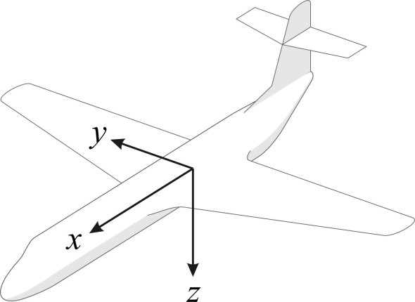
In principle, an aircraft can move in six different ways. Three of them are ‘translations’, in which the machine moves bodily along one of the three axes \(x\), \(y\) and \(z\) as shown in figure 1. The others are rotations about the three axes. The frame of reference can be defined is several different ways, but for our purposes we’ll take the axes as attached to the aircraft itself, so that the origin is fixed to the vehicle’s centre of mass with the \(x\)-axis pointing in the forward direction along the axis of the fuselage. The \(y\)-axis is fixed at right-angles to the \(x\)-axis, pointing horizontally to starboard, and \(z\)-axis pointing downwards at right-angles to the other two.
Aircraft stability is mostly concerned with rotations about the \(x\), \(y\) and \(z\) axes, motions that are respectively known as roll, pitch, and yaw. But in addition, there is also sideslip, a bodily motion sideways in the \(y\)-direction. From a stability point of view, we are particularly concerned about unplanned motions that are triggered by external factors such as wind gusts, initially small movements that take place without any specific action from the pilot. For example, pitch is rotation about the \(y\)-axis. A change in pitch may be caused by a local change in the vertical component of the oncoming wind, an updraught or downdraught that temporarily changes the angle of attack. When the angle of attack changes, the resultant lift force will move forwards or backwards, which may increase or decrease the pitch angle relative to the oncoming air, thereby exacerbating the disturbance. Pitching motions can mostly be analysed and modelled independently of the other two, because they take place within the machine’s longitudinal plane of symmetry, and if an aircraft pitches up or down, there’s no reason why it should roll or yaw at the same time. But roll and yaw are different. They tend to arise together, as components of a more complex pattern of motion taking place in three-dimensional space.
Coupling
Figure 2
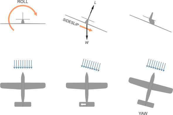
To understand how this happens, we’ll suppose that the aircraft flying straight and level, and imagine that a brief disturbance makes it roll to the right. You may recall from the discussion in Section A1610 that when an aircraft rolls, the lift force no longer balances the aircraft’s weight. In figure 2, we see the lift force angled to one side with the resultant force dragging the aircraft downward and to the right. The lateral component of motion is called sideslip, the aircraft is now travelling at an angle to its original course, in other words it has yawed to the right. As we’ll see later, other events may follow but for the moment we’ll note that through the mechanism of sideslip, starboard roll is coupled to starboard yaw. Following the same line of reasoning, we deduce that rolling to port is coupled to port yaw.
Figure 3
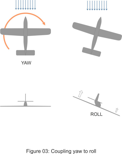
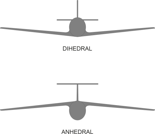
Now let’s repeat the experiment, only this time we’ll picture a different kind of disturbance in which the momentarily, the aircraft is yawed to the right (figure 3). The left wing is further forward than the right wing, in a place where the downwash created by the trailing vortex is reduced a little. Also, the right wing is shielded from the oncoming stream by the fuselage. The result is that the left wing rises. The effect is magnified if the wings are fixed at an angle to the fuselage as shown in figure 4. If the wings are angled upwards, they are said to have positive dihedral, and if they are angled downwards the dihedral angle is negative. Most aircraft have positive dihedral, so that when yawing to the left or right, the forward wing has effectively a greater angle of attack. This raises the lift further and magnifies the rolling moment. To summarise, starboard yaw is coupled with starboard roll, and port yaw is coupled to port roll.
Figure 4
You can see there is a certain symmetry here, and it is because of this coupling that the behaviour of an aircraft in roll, yaw and sideslip is different from its behaviour in the longitudinal plane of symmetry. We refer to its stability in this sense as lateral stability, while stability within the longitudinal plane of symmetry is called longitudinal stability. For practical purposes, the two can be handled separately.
Levels of stability
What is stability? If an aircraft is flying in a straight line and the pilot lets go of the controls, one hopes it will remain in the same attitude and continue to point in the same direction. The same applies if it is disturbed by a brief gust of wind. We are interested in how the machine might respond: we don’t want it to veer off-course or plunge to the ground. This requires that any small deviation results in aerodynamic forces that tend to restore the machine to its original course. This applies not just to aircraft, but to all kinds of vehicle: the family car doesn’t suddenly veer off the road if the driver lets go of the steering wheel.
Initially, we’ll focus on the short-term response, which comes under the general heading of static stability. An aircraft is said to be statically stable if, following a disturbance, it returns towards its original state without any input from the pilot [2]. By contrast, the wings and tail of a statically unstable aircraft will amplify the disturbance so it does the opposite. The case in which the aircraft’s response causes the departure to get worse is called divergence. You’ll have guessed that static stability implies an easier workload for the pilot. A statically stable aircraft will fly steadily with the pilot’s hands off the controls, with the ailerons, rudder and elevator control surfaces free to move in reaction to changes in the air flow over the wings and tail. Alternatively, assuming the aircraft is trimmed and flying in a steady state, the pilot can hold the controls firmly in place. Although we won’t go into detail here, these two situations, known respectively as ‘live stick’ and ‘dead stick’, lead to different levels of stability. In general, if flown live stick, an aircraft will be less stable than if flown dead stick.
What we’ve just discussed is only a snapshot in the way an aircraft adjusts to turbulence and other disturbances in the atmosphere. Even if the restoring forces are ‘convergent’ this doesn’t guarantee stability because we haven’t taken into account what happens in the long term. Once the aircraft is swinging back towards its initial state, the forces continue to act, and once the airframe has acquired momentum, the aircraft can pass through the initial state and veer in the opposite direction while the restoring force simply changes sign. Hence, the vehicle may overshoot and continue to oscillate around its reference position. We are now dealing with ‘dynamic stability’, and the question becomes one of damping. If the amplitude of the oscillations falls over time, the aircraft is dynamically stable, but if they increase without limit, it is dynamically unstable.
This is not necessarily dangerous, because a pilot can handle slow divergence manually [4], and in fact, ‘complete’ stability may make an aircraft sluggish, making it more difficult to carry out essential manoeuvres. In fact, many decades ago, aeronautical engineers realised that a combat aircraft would perform better if it was only just stable, or even unstable to a small degree. Equipped with an electronic computer to adjust the pilot’s control commands, an aircraft could fly in a predictable fashion yet still turn very quickly if it came under attack. But this doesn’t apply to transport aircraft, for which a safe and predictable response to disturbances is essential.
Longitudinal stability
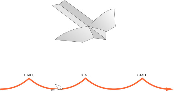
As a boy I used to play with paper planes and gliders made of balsa wood. Under my father’s guidance, I soon discovered that the position of the centre of mass was important. Too far back, and the glider would proceed in a series of swoops. Each swoop started with a dive after which it levelled out and began climbing upwards again. As the nose pitched up, the glider lost speed until it stalled and the cycle was repeated (figure 5). The problem could be cured by adding weight to the nose until the model flew steadily ahead, losing height until it landed on the ground. This all made intuitive sense, but I didn’t know at the time that it was a classic example of unstable behaviour.
Figure 5
Stability in pitch
At the heart of the problem is the overall pitching moment \(M\) that acts within the longitudinal plane of symmetry as a result of the aerodynamic forces acting on different parts of the aircraft. When it is flying straight and level, they balance each other out and \(M\) is zero. But as can be seen from figure 6, if the oncoming wind changes direction so that the angle of attack increases, the forces change. First, there is a rise in the lift force \(L\) produced by the wings. Second, there is a change in the vertical force acting on the tailplane. Thirdly, with a cambered wing, the centre of lift moves forward along the wing chord: the higher the angle of attack, the more concentrated the suction force near the leading edge of the upper surface. In different ways, all of these affect the pitching moment \(M\). Ideally, we want it to pitch the nose downwards, thereby reducing the angle of attack and restoring the aircraft towards its original position so that the pilot does not have to keep correcting the angle of pitch. Less desirable is the alternative outcome, that \(M\) acts in the opposite direction and raises the nose, making the problem worse.
Figure 6
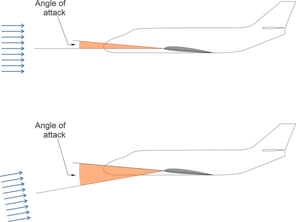
Figure 7
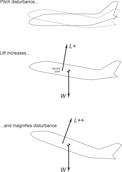
To be certain of the outcome, we must look at the effect of the lift and pitching moment combined. It is usually possible to determine a point along the aircraft plane of symmetry known as the neutral point. At this point, the pitching moment remains approximately constant as the angle of attack changes. It therefore acts as a useful reference location. If the lift \(L\) happens to be located at this point, we know that when the aircraft pitches upwards the only change in the aerodynamic forces is an increase in \(L\). Now imagine a brief gust of wind increases the angle of attack. We can picture the result as shown in figure 7, which shows an aircraft with neutral point located ahead of the centre of mass. When the aircraft pitches upwards, the lift continues to increase. This creates an additional torque that raises the nose further and makes the aircraft statically unstable. In figure 8, we see a different situation: the neutral point is located behind the centre of mass, so that when the aircraft pitches upwards and the lift rises, it tends to rotate the aircraft nose down, restoring it towards its initial position. This configuration is statically stable.
Figure 8
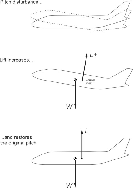
There is, however, a complication. If the neutral point lies behind the centre of mass as shown, the aircraft cannot be in equilibrium. The weight of the aircraft and the lift force together create a downward pitching moment, added to which there is a downward pitching moment \(M\) arising from the cambered wing. Since the overall moment must be zero for stable flight, a negative pitching moment must be supplied from some other source. For most commercial aircraft, this comes from the tailplane, which is set at a negative angle of attack as shown in figure 9. The disadvantage of this arrangement is that rather contributing to the total lift, the tailplane reduces it, which to some designers in the 1980s to be a waste. It was partly this realisation that inspired the development of the canard layout for light aircraft, with the horizontal stabiliser mounted ahead of the wing at a positive angle of attack.
Figure 9
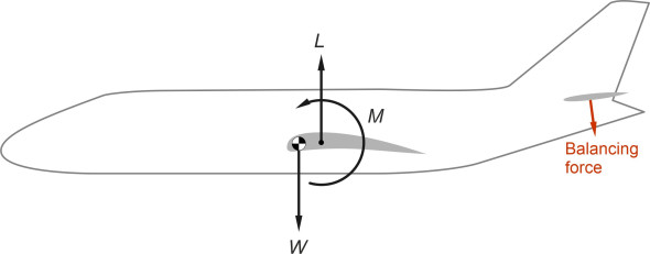
Stable and unstable configurations
To summarise, we expect an aircraft to be stable in pitch in the static sense if the neutral point lies behind the centre of mass, and the greater the distance \(h\) between the two, the greater the restoring moment and the more stable the aircraft will be. In this sense, \(h\) is a measure of stability, known as the static margin. Its value is important in a practical sense because the location of the centre of mass varies from flight to flight depending on how the cargo is loaded. In fact, it can vary during any particular flight as the engines consume fuel, and in the case of an airliner, as the passengers and crew move around the cabin. For most aircraft, the static margin is quite small, of the order of a few centimetres, which presents the designer with a challenging problem: to estimate with sufficient accuracy the position of the centre of mass relative to the neutral point. To find the centre of mass, one must go through every component of the aircraft and establish its weight and location, together with any change that might occur in service. Finding the neutral point is more difficult. It requires an estimate of the aerodynamic forces acting on each part of the aircraft skin, taking account of interference between adjoining areas such as the engines nacelles and wings, together with the effects of downwash on the tail, for example. We won’t go into detail here, but you can find more in [1] and [9].
All the above relates to the question of static stability, the tendency of the aircraft to return towards its original attitude following a temporary disturbance. This takes us to the most interesting aspect of longitudinal motion: dynamic stability. It is standard practice to design a commercial aircraft so that it is dynamically stable as well as statically stable. After a disturbance such as a gust of wind, if it does not pitch out of control, the aircraft will either return to its reference angle of pitch of its own accord, or alternatively, oscillate about its reference position with the oscillations dying away. Typically, a commercial aircraft has two distinct modes of pitch oscillation. The first has a relatively long period, of the order of 20 – 60 seconds. Termed phugoid oscillation, it takes place through the interchange of potential and kinetic energy as the aircraft climbs a little and descends again with each rise and fall in pitch. The second mode involves a more rapid oscillation as the nose pitches up and down. For the Boeing 747 jet airliner, the period of the phugoid mode has been quoted at 93 s, with a short-period mode of around 7 s, both modes being dynamically stable [6].
Speed stability
Figure 10
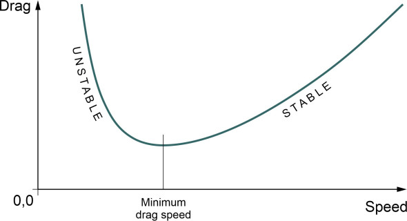
Hence, we see that pitching oscillations are accompanied by speed oscillations, which for a stable aircraft are relatively small and damp down with the pitching oscillations of their own accord. But there is another form of speed instability that is divergent and potentially a threat to the safety of the aircraft if ignored. We first came across it in Section A1215. Speed instability in turbojets arises from the nature of the drag vs speed curve, which is roughly U-shaped with minimum drag at a particular speed, the ‘minimum drag speed’ (figure 10). When a turbojet is travelling at a speed less than the minimum-drag speed, its pattern of behaviour becomes unstable – if the airspeed falls owing to a wind gust, say, the drag increases. The rising drag means that the speed will continue to fall, which without action from the pilot, will result in a stall. The opposite effect occurs when the airspeed is higher than the minimum drag speed, because a fall in the airspeed results in less drag and the aircraft speeds up again of its own accord. With turbojet-powered aircraft, the phenomenon becomes a serious problem when landing, because the landing speed for a modern commercial aircraft is usually well below the minimum drag speed, and their response to throttle changes is relatively slow. It is tackled by installing air brakes and flaps, which move the minimum drag speed to a lower value.
Lateral stability
Now we turn to the lateral motions: roll and yaw. For the moment, we are concerned only with static stability: the short-term response of the aircraft to a disturbance. At this level, it’s useful to consider the factors that influence stability in roll separately from those that influence yaw. Later, we’ll go on to examine two modes of instability that embrace both, these being fully-fledged motions in three-dimensional space.
Directional stability
Figure 11
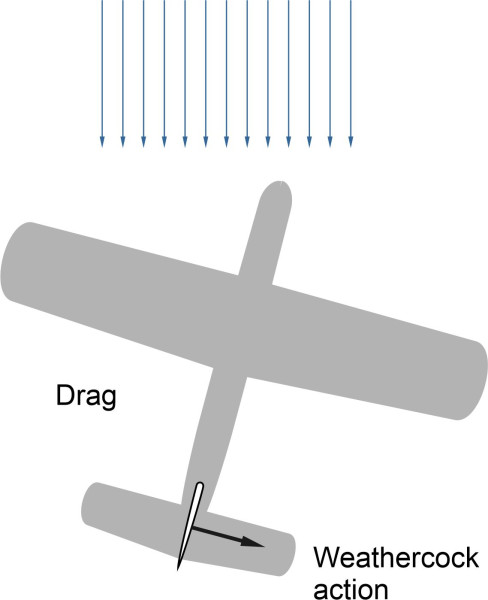
We begin with an aircraft whose wings have zero dihedral. Imagine it is travelling at constant speed in straight and level flight, when the direction of the wind changes so that temporarily, the aircraft is yawing to starboard relative to the oncoming free stream (figure 11). As a result, there are changes in the aerodynamic forces acting on different parts of the aircraft. The most important is the vertical fin. It acts like a weathercock, creating a restoring moment that swings the aircraft back towards its original state of zero yaw – in other words, it makes a positive contribution to stability. There is also the fuselage, which has a characteristic shape: long, narrow and of approximately circular cross-section. In normal flight, its axis of symmetry lies parallel to the direction of flight, as are other parts that have no particular aerodynamic function such as engine nacelles and wing tanks. But if the aircraft yaws to starboard, for example, they will all point a little to the right. Unlike the fin, these body parts don’t contribute to stability – in fact they do the opposite. You may recall from Section F1816 that when considered in isolation, following any disturbance, such bodies tend to swing away from their initial position, making the aircraft unstable in yaw. Since the stability of an aircraft depends on two opposing influences, the size of the fin is crucial: for a transport aircraft, it should be large enough to dominate the outcome. It’s a salutary thought that without a fin, the natural tendency of an aircraft is to fly sideways.
Instability in roll
Figure 12
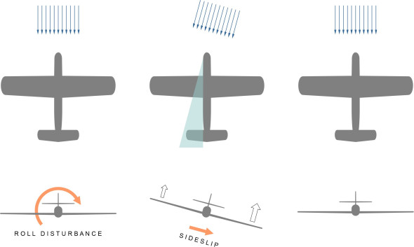
Now let’s repeat the thought experiment with the aircraft in straight and level flight, and imagine this time that a gust of wind causes it to roll a little to the right. We’re concerned with the initial response: will tend to roll back towards its initial state? With aircraft viewed from the rear, figure 12 shows how the port wing lies within the fuselage ‘shadow’, in the sense that the oncoming air flow now arrives at an angle to the fuselage. It flows partially over the top and underneath, so that fuselage leaves a wake extending laterally to port, and the air is no longer flowing smoothly over the root of the port wing. Hence the lift falls, creating a rolling moment in the opposite direction to the original roll disturbance. Although weak, this is a statically stable response. The restoring moment is assisted by the fact that the port wing is also trailing a little behind, in a region where the wing downwash is greater, which further reduces the lift [5].
Figure 13
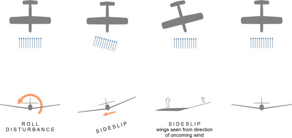
In practice, most aircraft have their wings fixed to the fuselage at an angle, sloping upwards towards the wingtip. The upward slope is known as dihedral, and it improves the aerodynamics. Figure 13 shows the aircraft the other way round, as seen from the front. When it rolls to starboard and sideslips, the starboard wing moves through the air at what is effectively a higher angle of attack than the port wing. It produces more lift, which greatly increases the restoring moment. Hence, dihedral is an effective and practical way to improve roll instability.
Spiral instability
Now we turn to a mode of instability that involves both roll and yaw. It has been known to pilots for decades and has caused many casualties. It is known as spiral instability, and it arises particularly when the aircraft has a large fin but low dihedral – in other words it is directionally stable but not very stable in roll [8]. Under certain conditions, such an aircraft can enter a ‘spiral dive’ that if not dealt with by the pilot, can lead to a steep descent from which the aircraft may not recover. As before, we begin with the aircraft flying straight and level, as shown from behind at the top of figure 14. Then a gust of wind causes the aircraft to roll a little to the right. As we know already, starboard roll leads to starboard yaw and vice versa, and without corrective action from the pilot, the process may become self-reinforcing or divergent. It also causes the nose to drop, so the aircraft accelerates at an increasing rate of descent into a spiral dive. A similar result can arise when the pilot makes a steeply banked turn and allows the nose to drop too far in sideslip [8].
Figure 14
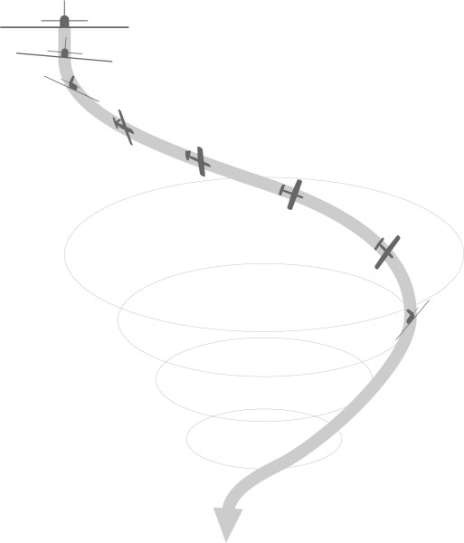
For any particular aircraft, it is not unusual for the spiral mode to be unstable over a range of flight conditions [7], but the process is sufficiently gradual for the pilot to recover without difficulty. On the other hand, it can lead to trouble, for example when flying a light aircraft inside a cloud, or at night when the pilot cannot see the horizon. Normally, the pilot can fly ‘by the seat of the pants’, using inertial forces acting on the pilot’s body to judge what the aircraft is doing, but in a spiral dive, there is little to go on, and it is easy to misjudge the situation. From a design point of view, the key to avoiding spiral instability to find a suitable compromise between the fin area and the angle of dihedral.
Dutch roll
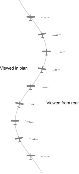
Finally, we turn to the Dutch roll. This is a phenomenon that caused problems during the early days of flight, and later became a serious issue for modern jet aircraft. It is characteristic of machines with that have large roll stability but less directional stability, the opposite of the case for spiral instability. Many jet aircraft come into this category, having swept wings that as described earlier, give them good roll stability and therefore have a divergent Dutch roll [8]. For this reason, many are equipped with autopilots that damp the behaviour automatically. Assuming the intended course of the aircraft is a straight line, the Dutch roll amounts to a series of lateral oscillations from side to side, with the aircraft rolling alternately to port and to starboard as shown in Figure 15. In comparison with the spiral dive, which has a comparatively long period, the motion has a comparatively short period of between about 3 and 15 seconds. The two forms of instability are said to be analogous to the short-period oscillations and the longer period of the Phugoid in longitudinal control.
Figure 15
Conclusion
Transport vehicles sometimes move in ways that designers do not expect. During the nineteenth century, when travelling at speed, the coaches of a stream train would lurch from side to side. Motor cars would ‘oversteer’, magnifying the drivers’ steering commands so they became difficult to control. If a ship lost power in a storm, it would turn sideways on to the waves, the worst possible angle from a sea-keeping point of view. It’s curious that a vehicle whose shape is symmetrical about its centreline can begin to oscillate sideways or break away from its course with no input from the pilot. Many of these problems were explained mathematically over a century ago, and have since been resolved. Railway trains and automobiles are more stable and behave in a more predictable way than used to be the case. But aircraft have taken longer. The aerodynamic forces acting on the wings, tail and fuselage are an order of magnitude more complex than the mechanical loads on a land vehicle, and designers still rely a good deal on wind tunnel testing and flight testing to check whether they are safe. Over the years, many test pilots have lost their lives in the process [3]. Fortunately, computer simulation can now assist the design process and reduce the risks involved. In the next Section, we’ll go on to consider how the pilot can exert control over the machine and execute the manoeuvres needed for a safe flight.